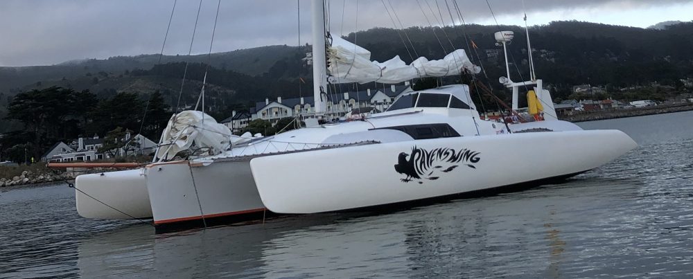
Here are a few more views now that the equipment tower is fabricated and faired. It will be getting a second horizontal ‘shelf’ but we’ll wait on placing that until figuring out if an electric tiller pilot (remote steering) can be mounted back there. This would be in addition to the primary windvane (no electricity needed) self-steering gear. We need to have the completed tiller in place first.
The legs have thru-holes for lifelines:
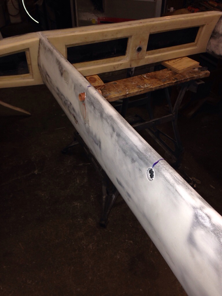
The top is a carbon deck and a simple hollow box below with access ports to hide the equipment fasteners and wires. The hole in the center of the platform is a channel to pass the windvane’s control lines down to the rudder trim tab. And the horizontal stick out the back is a little gantry for lifting and holding the rudder out of the water once docked or anchored. The ear flap on the starboard side is for the radar; the port side is flush son you can get to the aft steps easily.


I’m actually getting sick of the splotchy fairing patches look on all these big parts. It’s about time to get things primer painted so a cohesive boat begins to emerge. But we shouldn’t touch any painting until the fabrication work is complete.
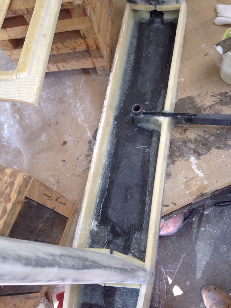
After the Jim Antrim meeting the steps on building the integrated trim-Tab rudder became clear, so work is underway. During careful placement of the 5′ carbon hinge tube, we had a “runaway thermal event”, meaning Greg blew it by trying to bond the 7/8″ carbon tube in to the centered 1 9/16″ channel cut into the foam core, and expecting to have that work in one fill ‘er up with epoxy putty pass. As I was seating in a uniform depth, the mass of wet epoxy down at the bottom was too great and it superheated quickly. Realizing the problem, I tried to yank the whole tube out and quickly evacuate the putty. Instead the carbon melted and bent the tube that needs to stay arrow-straight. What a huge mess, along with the panic of losing the very expensive 2 1/4″ shaped foam core and triple layer carbon spine. Here’s the work before the meltdown.
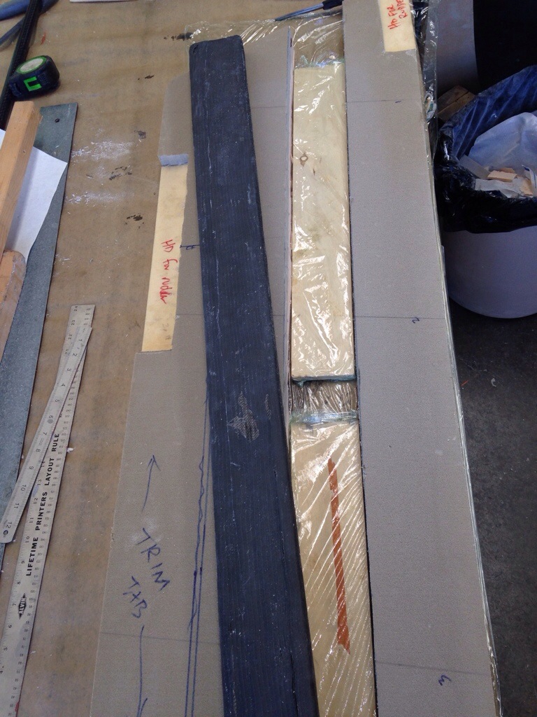 that’s the spine about to be bonded in – 3 layers of carbon around high density foam, then center the whole thing in the low density rudder core. Also see on the left side the marks for the trim tab – it’ll be 4 1/2″ of the 16″ wide rudder and run about 3′ vertically.
So Monday morning began with another $100 sent to Rockwest Composites in Utah to replace the pivot tube. Monday night ended with a nasty two hour job of extricating the ruined tube and hardened putty from the soft rudder core. skilsaw, router, grinder and multi tool teamed up to make a fantastic mess but in the end the channel integrity is back and ready to take the new tube once the UPS truck drops by. We’ll do the bonding in multiple stages this time. Another expensive lesson learned.

It’s late Monday night; I can’t figure out all the problems you described that just occurred – BUT – let me simply point out that a $100. plus mistake on a project as big as your boat is , is nothing more than a PIMPLE ON THE BACKSIDE OF AN ELEPHANT!!! In other words, don’t sweat the small stuff!!! I’ll see you Tuesday at noon at the boat. Love, Dad
LikeLike