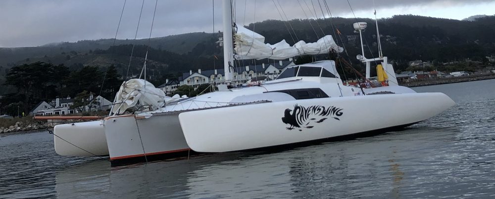
Not talking about Kevin Bacon here, but rather the need to rake the mast back three degrees from vertical. This tilt of the mast helps the sailing responsiveness and has been factored in to the exact mainsail shape (which is under construction in Maine right now). So we need to get this right.
We can’t stand the mast up, so we’re doing the math at 1/25th scale (2′ vs 50′). The cardboard wedge is 3 degrees wide:

We need a hardwood wedge under the steel mast foot to create the angle. The wedge is greater than the 3 degrees because the deck slopes away from level. Based on math measures, here was the first cut.

The alder hardwood block was planed to that black line but that yielded a 5 degree tilt, so some trial and error in hand shaping got it right.

The wood wedge was then clad in two layers of 12oz BD fabric. This piece was vacuum’d in an actual bag, not on the flat table. The bag pressing in on all sides if done right will put the excess glass right in the middle of each edge for an easy trimming job. This one went pretty well.

After some fairing putty, we tested it on deck today and hit right on a 3 degree rake at the mast foot.
We talked today about adding a piece of steel atop the wood wedge with the mast base you see above welded to the new plate. That way the bolts holding the whole thing to the deck would pass through steel. As it stands now, the steel square has to be bolted to the wood wedge and the wedge then bolted to the deck. The steel square isn’t wide enough to span the dagger slot and be bolted directly to the deck. Anyone have experience or engineering perspective on this?
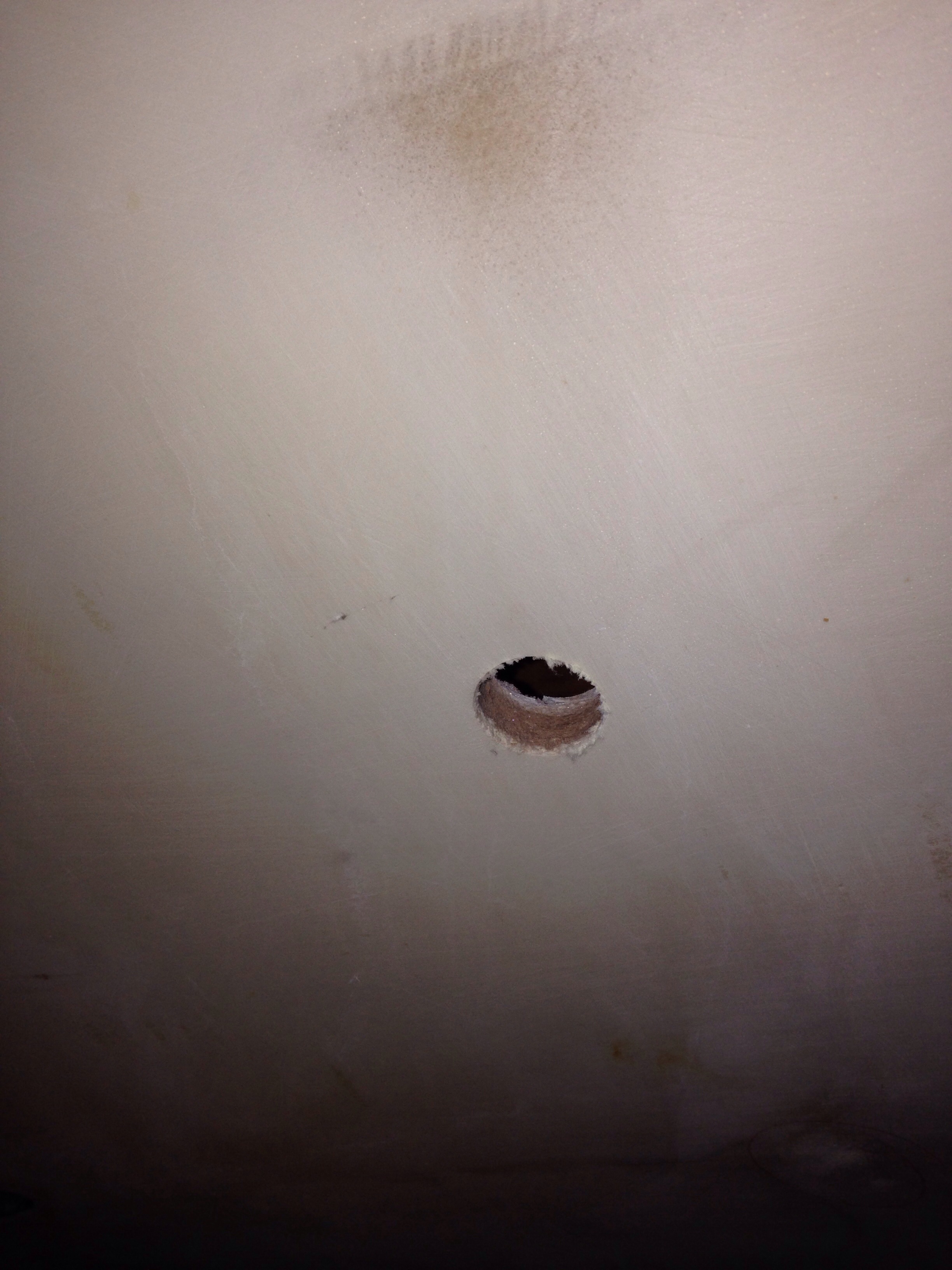
Today was spent on holes. First, a big one in the pocketbook, striking a good deal with Defender Industries. This order covers most of the big areas left – ports, plumbing, propane and remaining deck fittings. We did better here than Port Supply or other local sources. It’s been an incredibly rigorous and time consuming process to equip the boat, but the best part is going direct to manufacturers with the help of experts. We’re getting great gear from Lewmar, Colligo, Blue Sea electrical, New England Ropes and Garhauer. Thanks for your help guys!
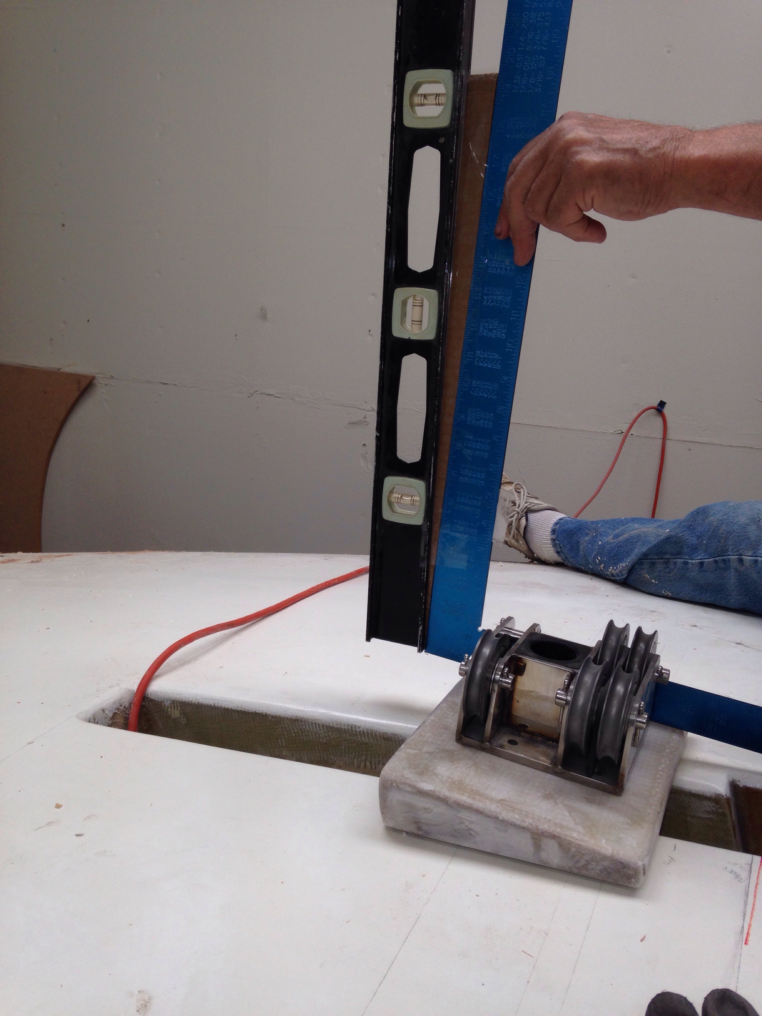
After giving Defender the Amex number, we tackled the first through hulls. We’ve made plumbing decisions such that there’s only one below-the-waterline plumbing hole (for a seawater manifold) and one for the depth sounder / speed sensor. They are going in tandem placement, just starboard of the daggerboard.
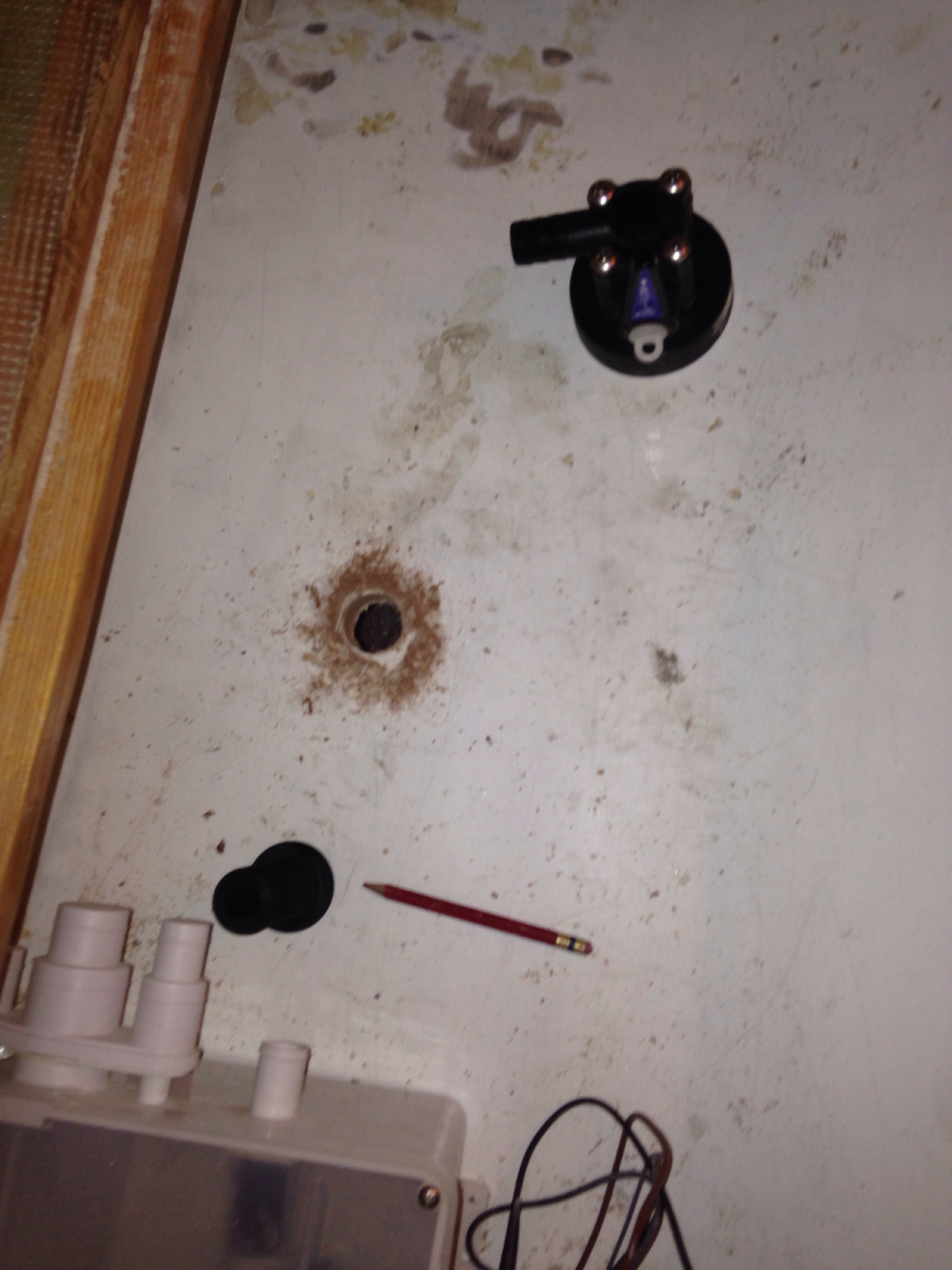
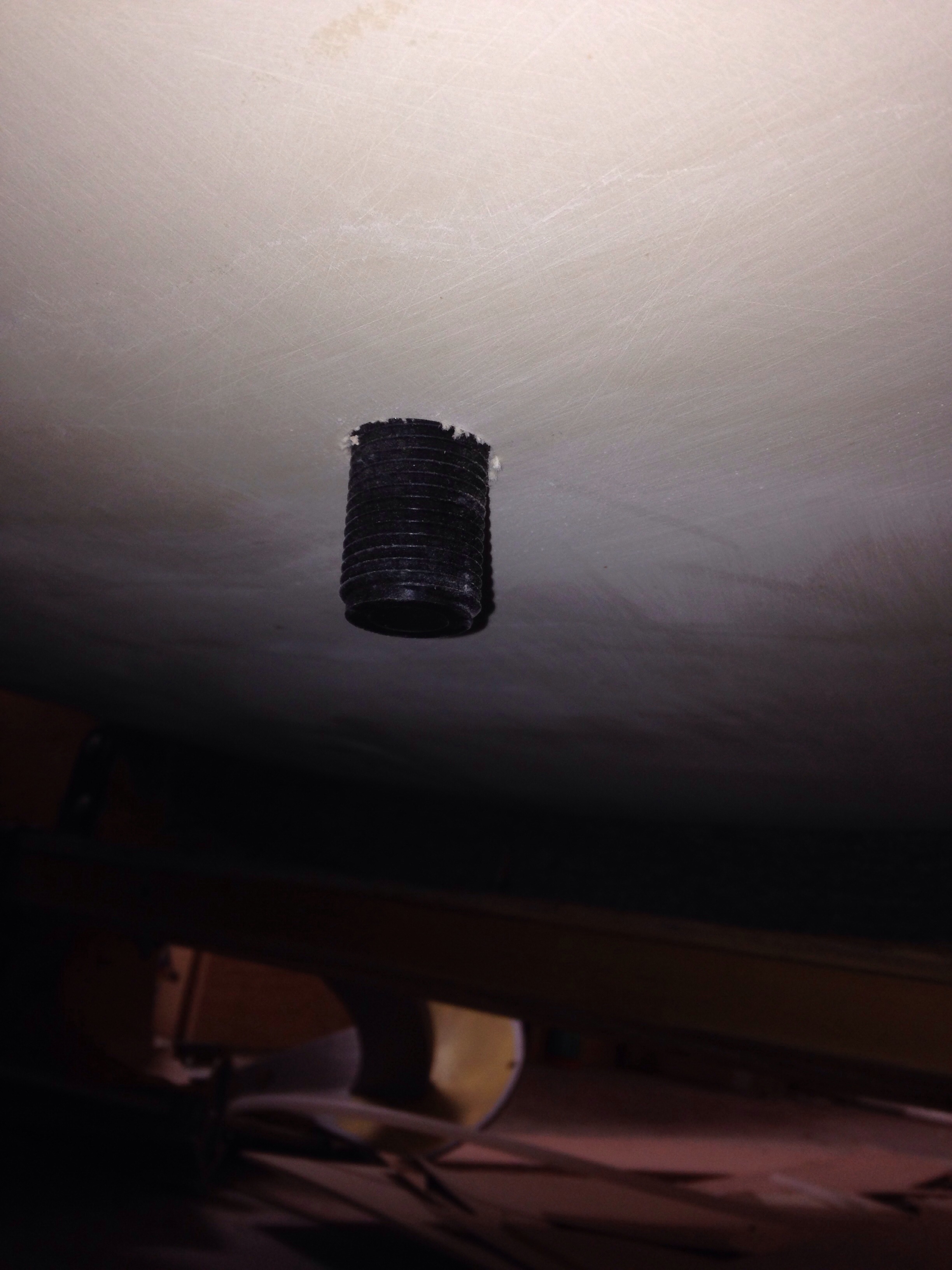
Here’s the thruhull inserted upside down to check the depth; we needed to cut off about a half inch of threads. In the second photo you can also see the Kevlar outer skin in the ‘shadow’ of fairing compound – that’s about two feet wide from the bow back towards the stern.
Further up the hull side, over on port, is the first above the waterline thruhull. This one is the galley sink.
All of these holes are being cut too big and then re-edged with epoxy/cabosil putty. We’ll also add back some glass on the outside and fair it in. I decided to do this instead of trying to dig out cedar core in between the original inner and outer glass layers. We’ll see more of the thru hulls during the post-painting fit out.
The main cabin is getting final furniture building. Here’s a cardboard mockup of a backrest cabinet for the seating position on the starboard day bunk. The base isn’t very wide and the hull curves in steeply, so it’s a tough balance to preserve lying down comfort yet make the backrest functional for sitting up. It doesn’t extend to the bulkhead in the left of the photo because that’s the most comfortable spot, leaning back on that locker wall with your feet up on the bunk. Thanks Charlie for the idea to make the backrest swing up to reveal a small storage cabinet.

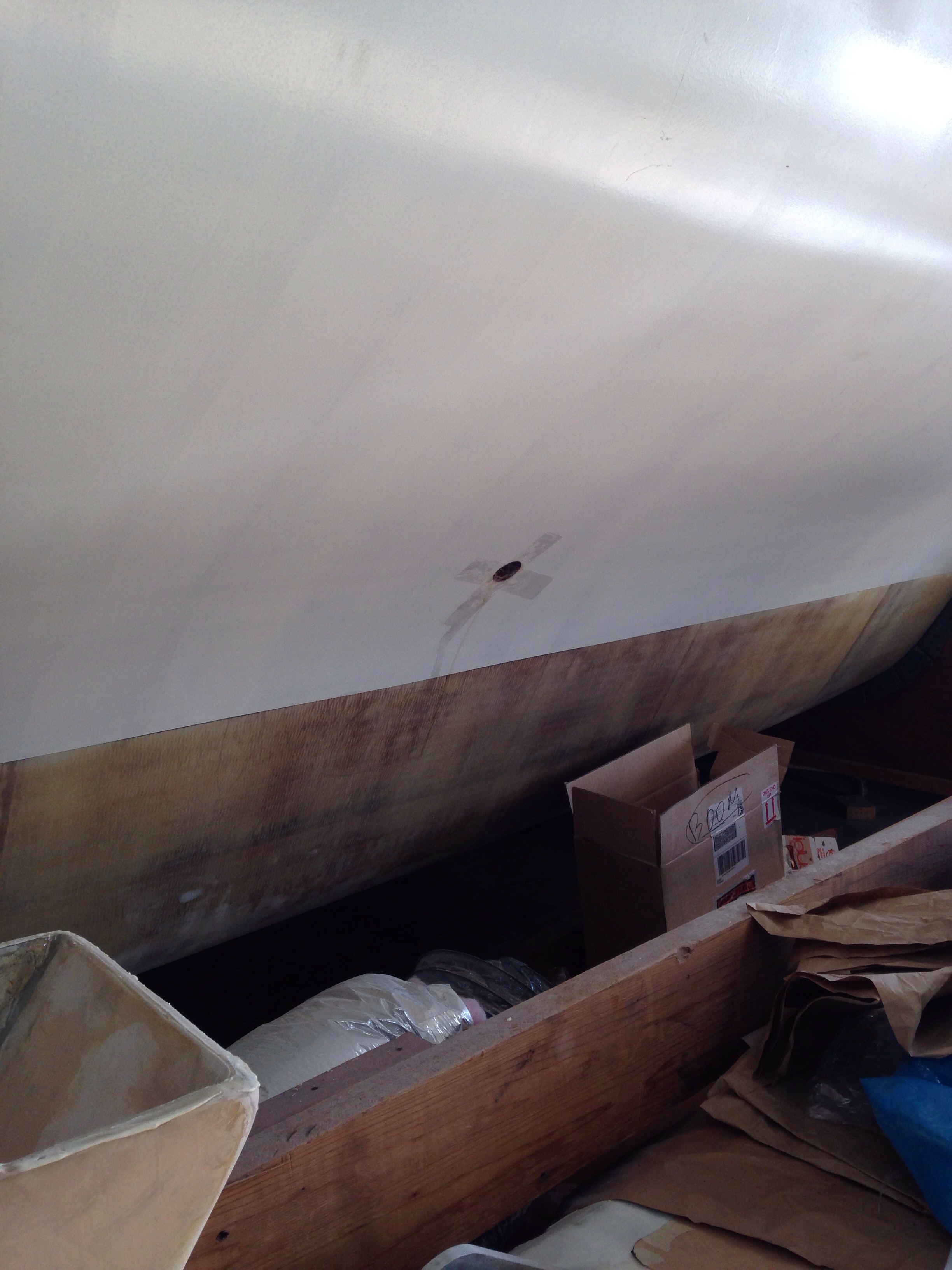
During the cabin buildout we think ahead to wiring – here the chart table gets surgery in the form of a big 4″ series of holes to route cables between the batteries and the circuit breaker panel. This stuff will get clean face plates screwed on to hide the wires after installation.

And we’re spreading mahogany dust all over the driveway as the portable mill rips and planes repurposed baseboards and casings in to lovely boat interior trim. The boards on the right end up as excess stock when cabinetry clients change their minds. Good neighbors to have during this build!
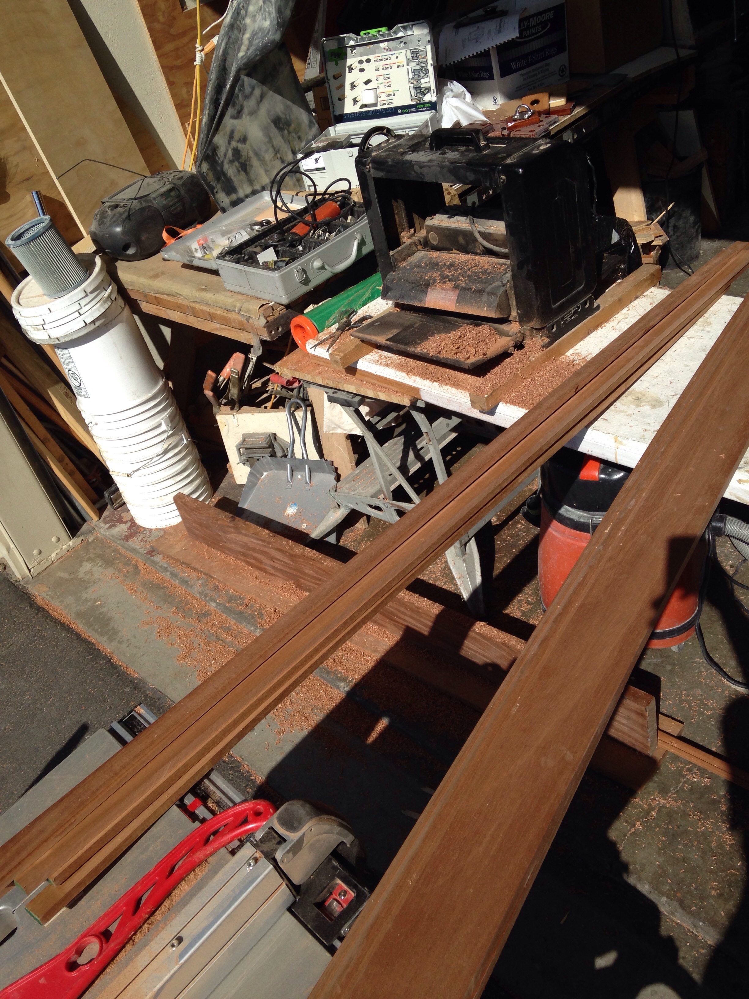
And so the pile grows, with a couple more days of fitting trim pieces inside, and when complete they will all get sanded and finished in the shop before bonding in to the boat. Painting day 1 inches closer…


Greg, on the mast base it’s 99% compression and a tiny amount of shear.Bury and bond hex head bolts inserted from below for the steel base fastening and from above for the wood block fastening.all with the hex heads below surface, faired over. After you finish paint the wooden wedge you instal the steel base with a little 4200 and snug the nuts then drop the whole nine yards, again with a little 4200, snug the nuts up from below, either side of the case and you are done. Clean and weather tight, hardly even need washers, it’s just location. If you add a steel plate it’s just weight with little structural contribution, unless it’s thick, then it’s lots of added weight!
LikeLike
Great, that matches what I was thinking. Only minor snag is two of the bolt heads sitting right under the halyard sheaves, not leaving room to go upside down with the nuts on top. But we’ll figure out a suitable bury. Thanks!
LikeLike
Pull the pins and lift out the double sheaves and use 1/2 nuts with rounded off upper corners for no-snag. Cut,file and polish the excess bolt length. Reassemble the sheaves and pin. OR you could forget the nuts and make subject bolts location dowels only. Sounds like Mr F put the bolt holes in the wrong spot.
LikeLike
This one’s on the builder. Designer calls for a complex, robust pivot ball mast foot that spans the dagger trunk, but we’re using a simple pivot pin box that came with the mast – it wasn’t intended to bridge a dagger slot. The Farrier piece looks to have about $500 of fancy aluminum welding involved. No thanks :)
LikeLike