$#!? rolls down hill

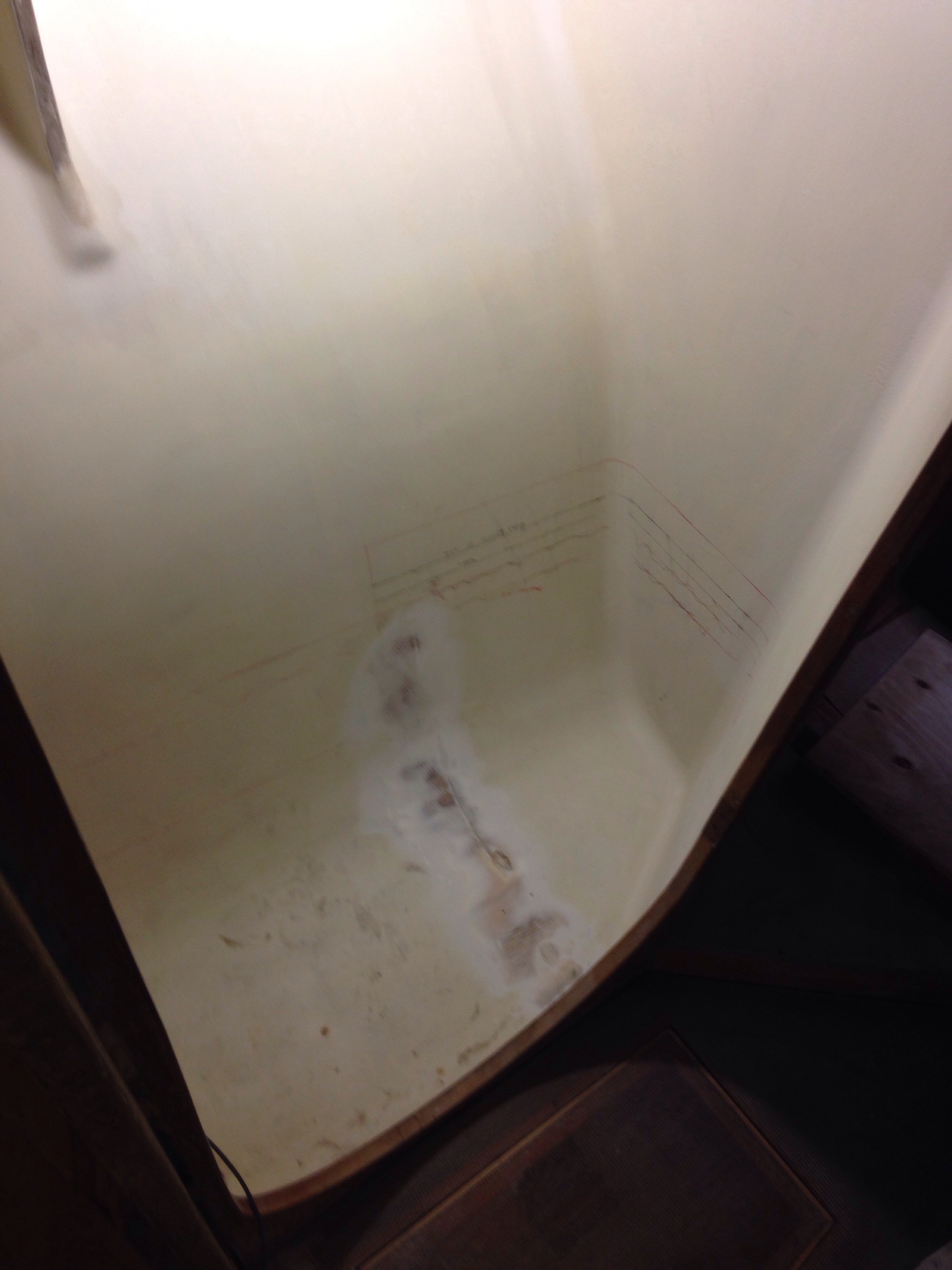
The bathroom is never big enough, right? Because our hull bottom is so skinny, the head compartment is cramped and every inch of space needs to be used efficiently. So what goes under the toilet – well, the holding tank makes sense. Thank you Mike L for insisting on that one :). One wants the “black water” tank as large as possible for lazy cruising days, so as to minimize trips to the dreaded pump out station. Rather than buy a expensive, too small tank, we made one that fills the space available. First the blank canvass …

20141222-174852.jpg
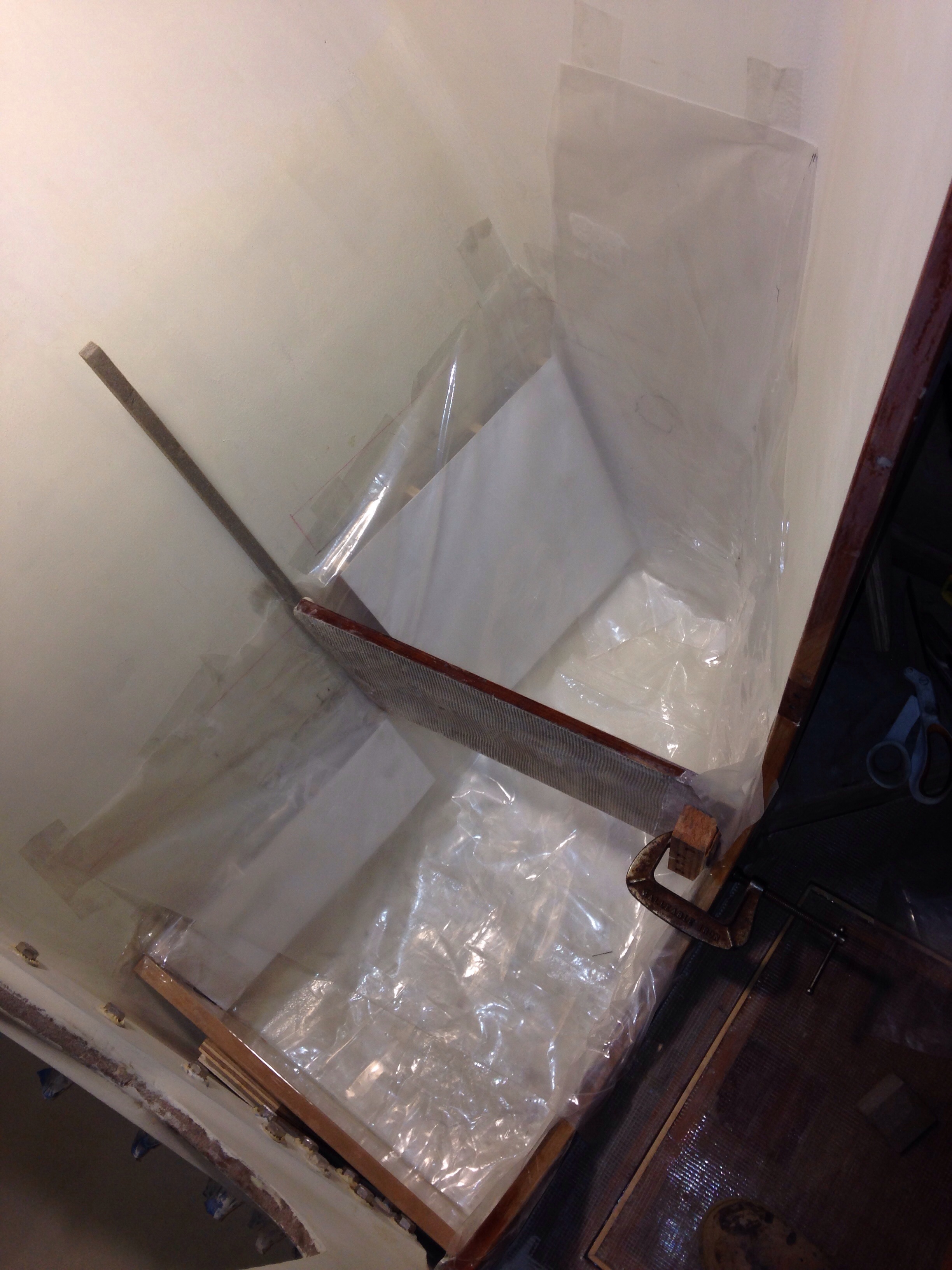
Now line it with plastic, but NOT like this. Using the loose bag produced nasty ripples along the bottom. Had to cut those out and redo with form-fitting plastic tape instead applied to the hull shape.

20141222-175043.jpg
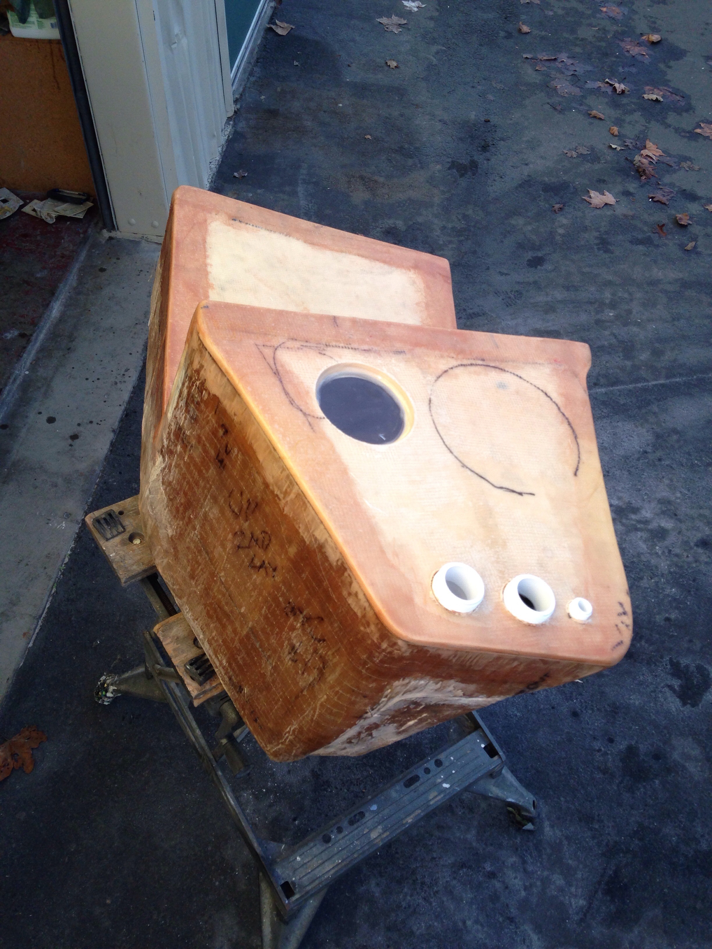
The L shape means the tank is both under your feet and under the toilet base.

20141222-175139.jpg
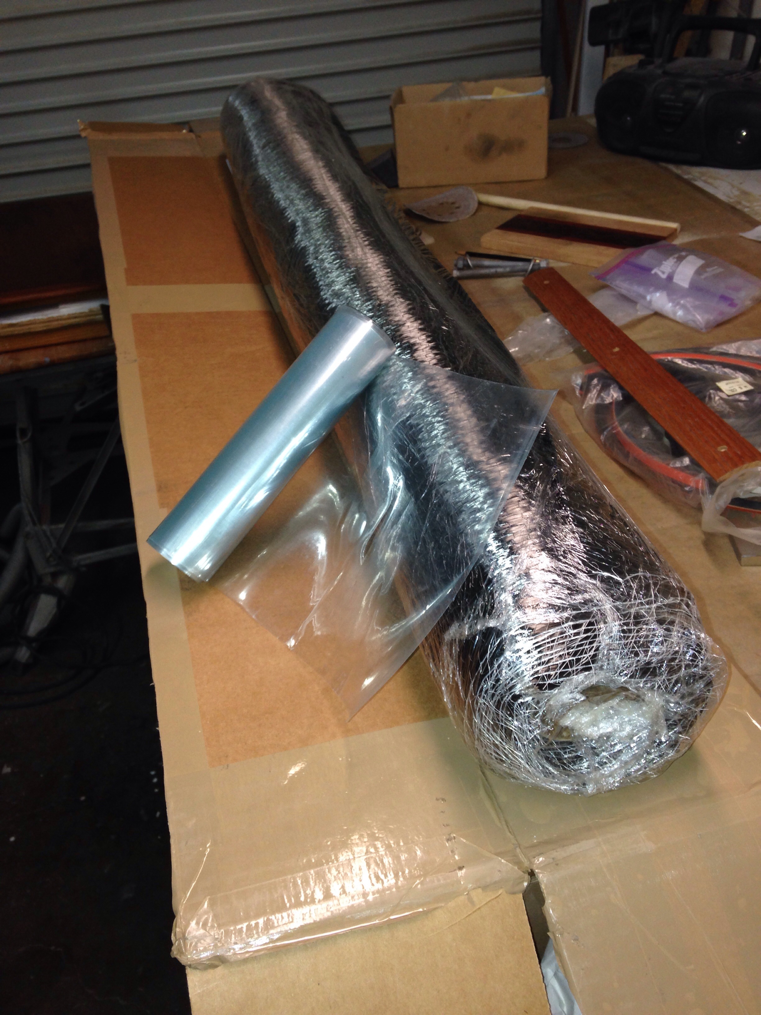
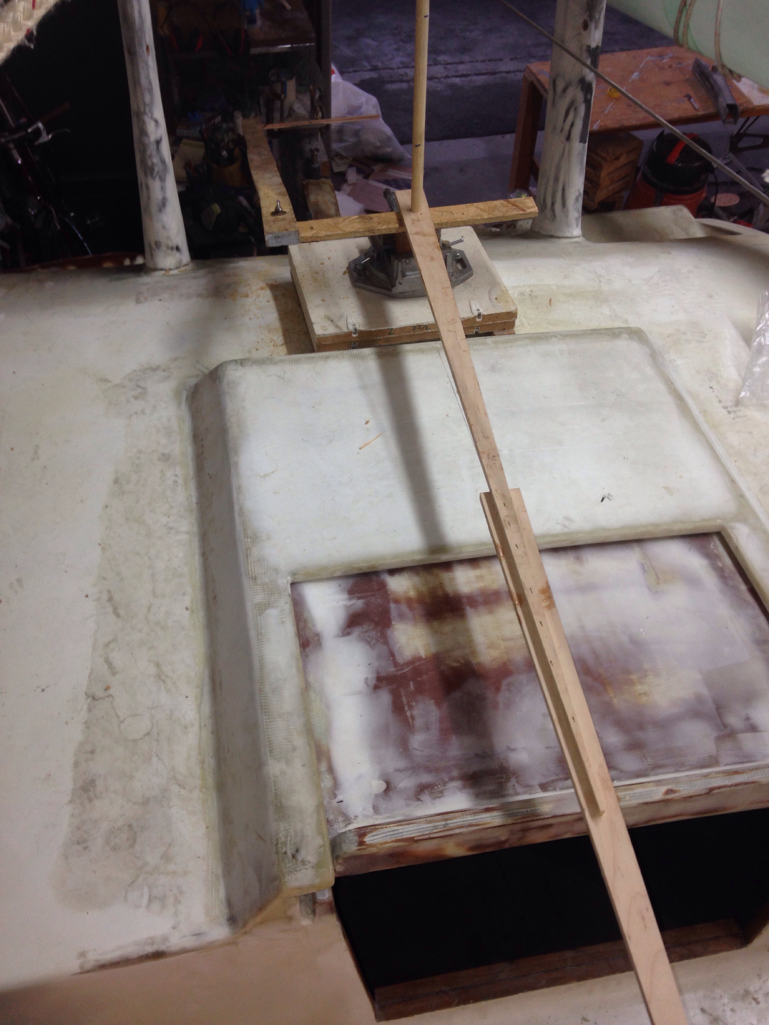
That whole unit lifted out after some prying, and the top pieces were made on the vacuum table. Along with some heavier laminations for the floor and shelf that will sit just above the tank.

20141222-175309.jpg

20141222-175325.jpg
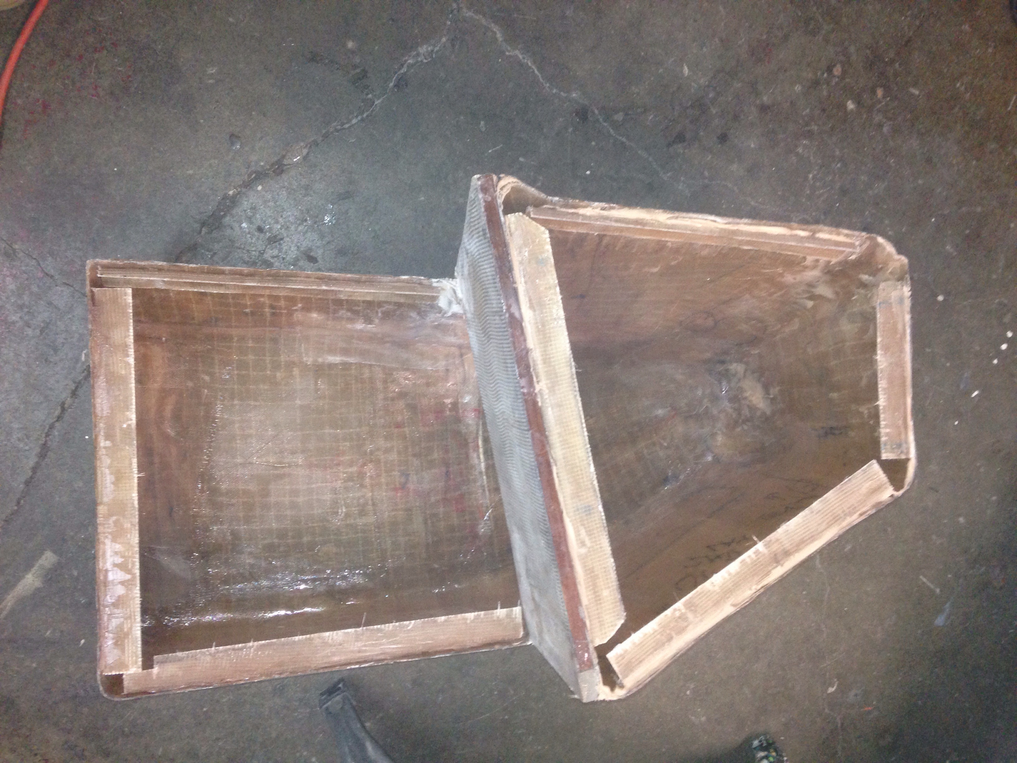
Rather ugly for my first ever tank build, but it held water under testing.
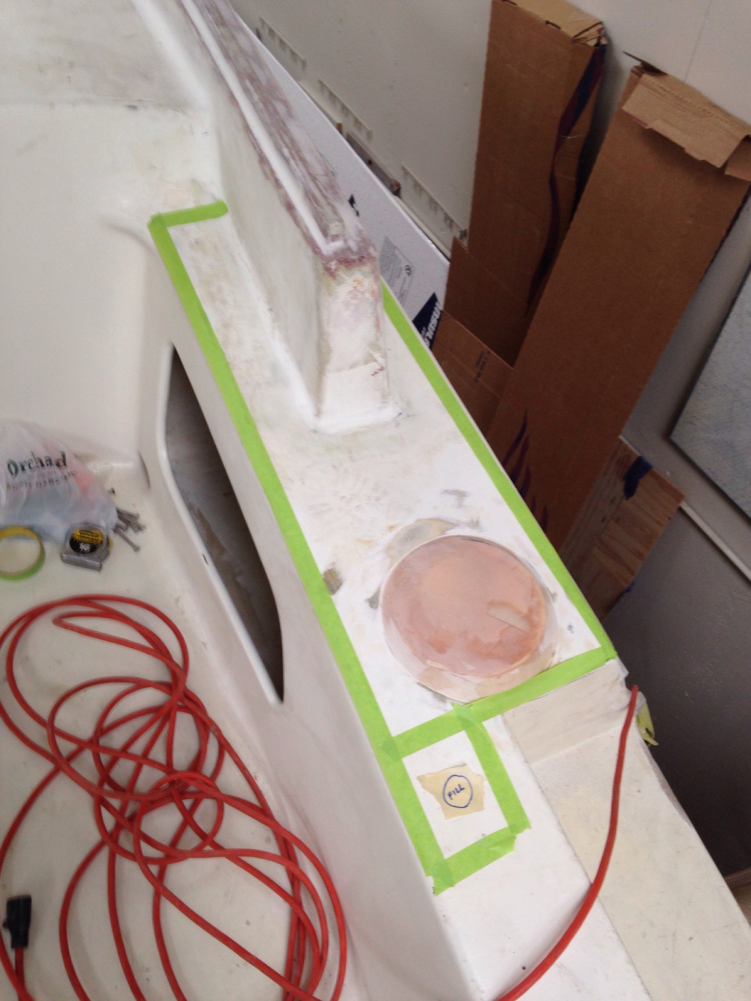
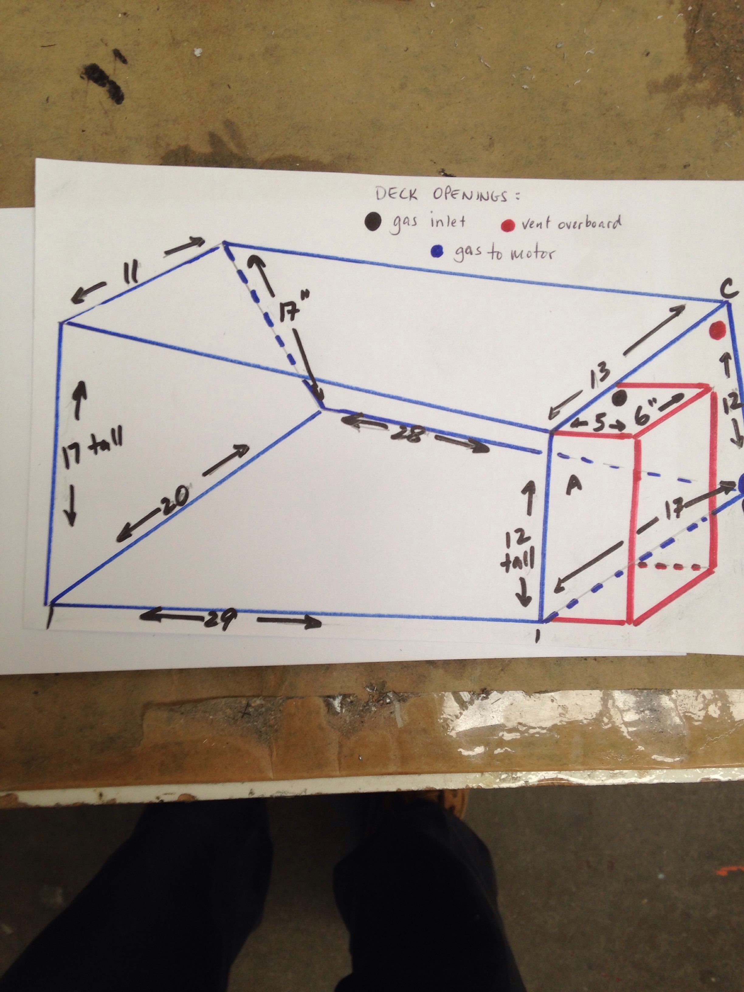
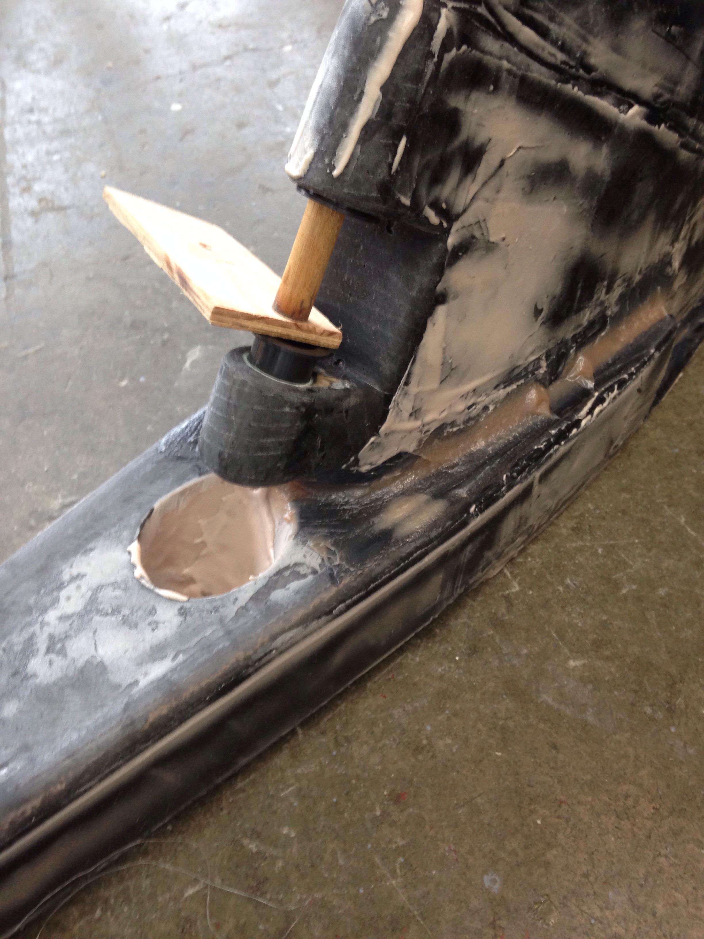
The outlet to the sea is at the bottom, while the inlet / dock pump out, the breather vent, and a spare clean out port sit on top. Rather than installing an expensive and wire-consuming monitor system, there’s a visual level gauge on top – a window we won’t inspect too closely!

20141222-175704.jpg
After sealing it all up, the tank slides in place. The hull-facing wall is inset 3/4″ to allow for a bonded-on high density bolting flange (on the wall, not the tank) that will take the weight of the toilet and user, as opposed to actually pushing down on the tank.

20141222-180010.jpg

20141222-180026.jpg

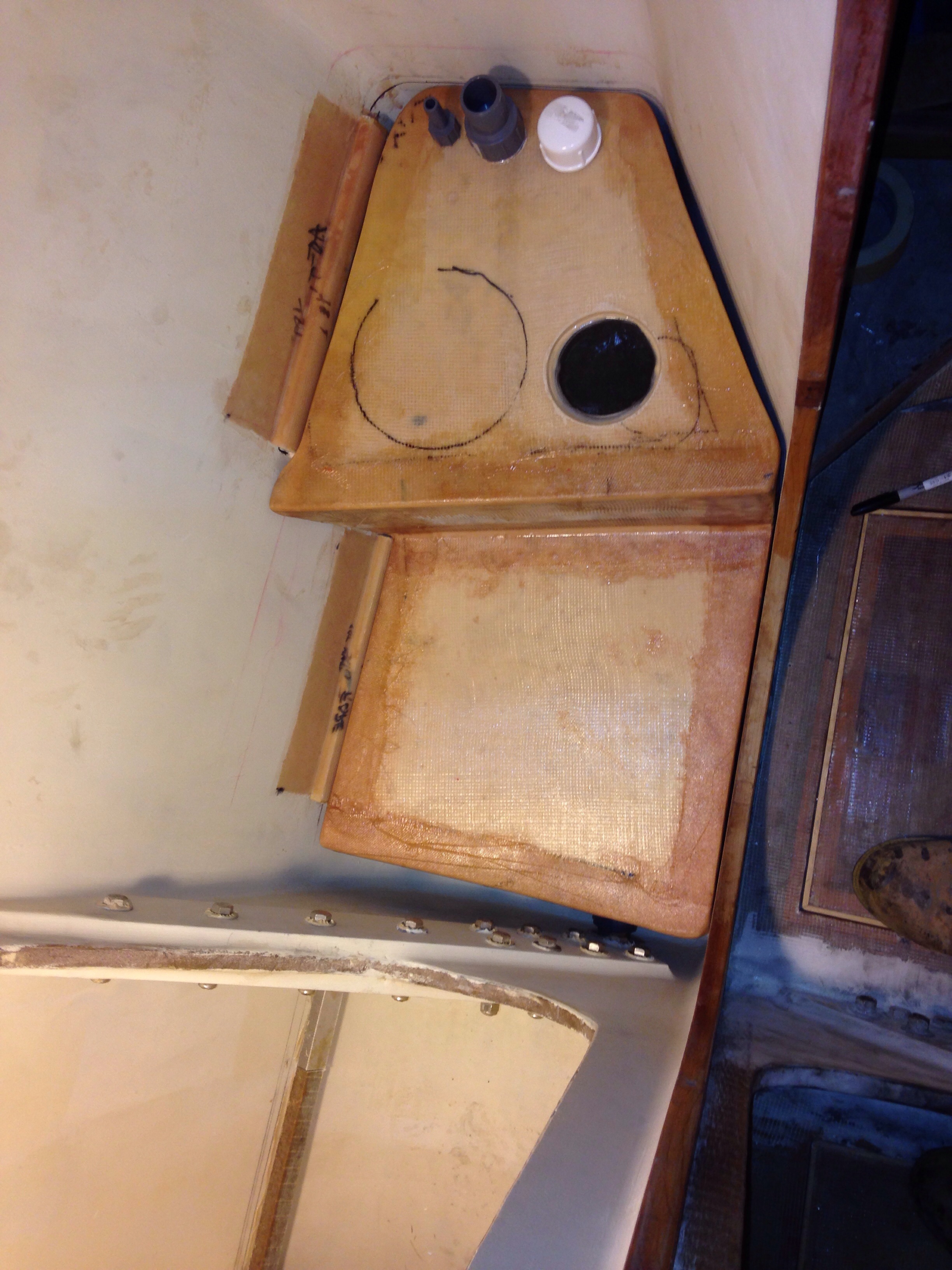
The black pen circle is where the toilet will sit on the shelf just above this tank, but the toilet is not connected to the tank. An exit hose runs from the back of the toilet, up through a pump and a loop up above the waterline, then down in to the tank. The good news is this design means no waste stays in the pipes, which is usually the cause of nasty smells. We’ll see the head installed and the shower floor come together in the next post, and maybe some cardboard mockups of vanity counter / cabinets.

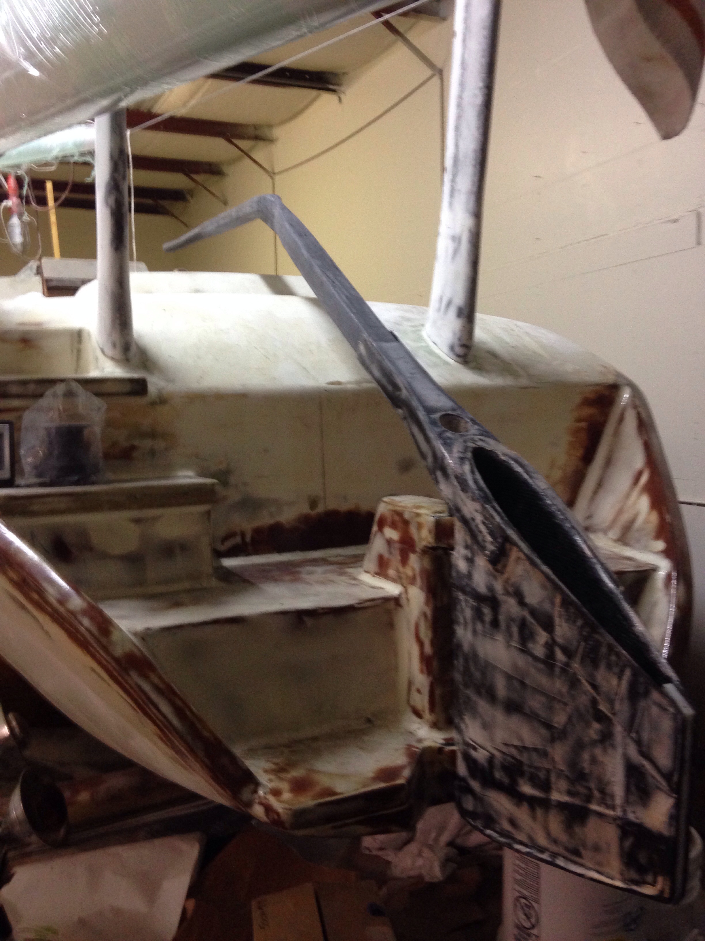
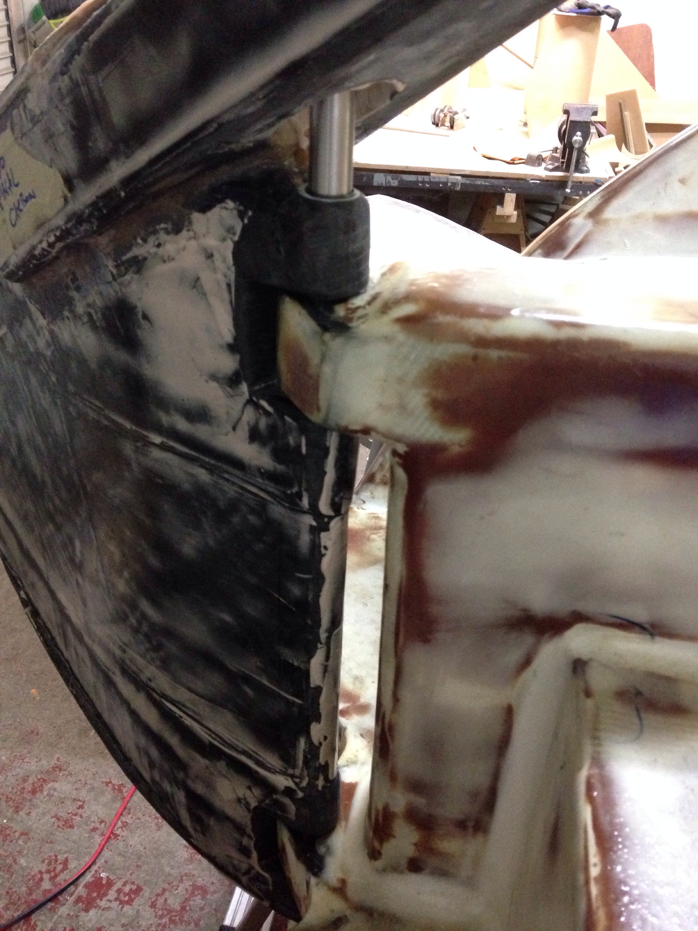
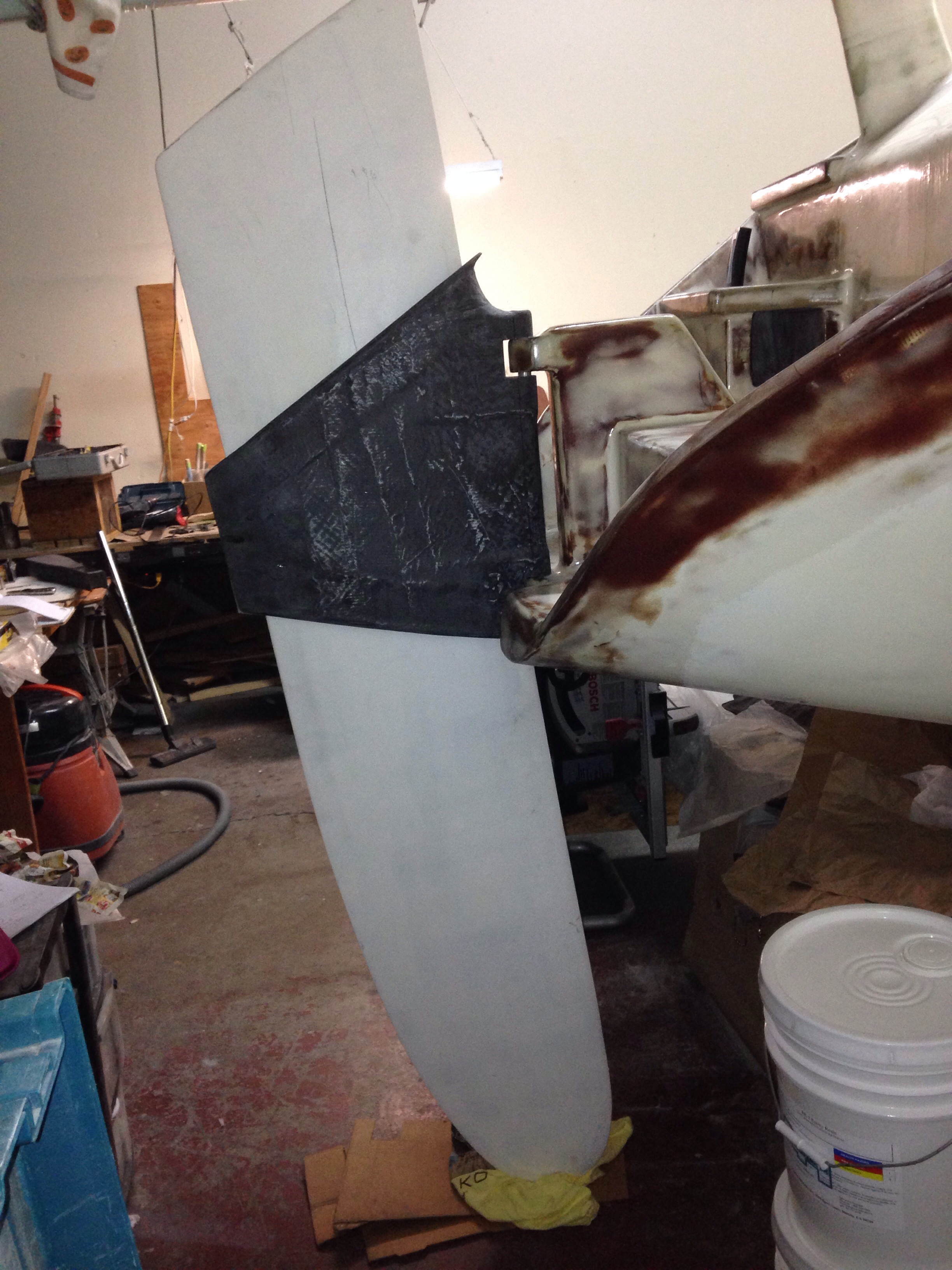
Back on deck, we hung the near finished boom in place and set up the Delta Vee main sheet. Well… The long-tiller steering isn’t going to clear so it makes sense to build a linkage steering system. Messed about with the geometry today until getting the right pivots and control arm lengths.

20141222-180436.jpg

20141222-180502.jpg
The steering action is fast and the tiller throw much shorter; this is a much better solution than the first, including a nice way to attach an electronic tiller pilot independent / redundant from the wind vane system. Farrier’s plans call for all this gear to be inside the aft cabin, but I saw that on a completed F39 and it really interferes with the cabin living space. Other owners would not like the steering gear exposed on deck, but I like the simplicity and obvious inspection ability of the gear in plain sight. Thinking of using a flanged rudder bearing to anchor the tiller pivot, and some combination of carbon bars and stainless steel rods & ball joints for the linkage. Type 304 SS ball joints are easily found – thinking we’ll use those and carry extras vs. hunting for rare type 316 SS ones. Any comments back about that?

Steering complete

The 9′ long steering tiller fit in to the rudder cassette head to complete this project. There is still cosmetic work to do, but it’s nice to know we could pilot the boat now if all this rain keeps flooding the county.

20141210-232905.jpg

20141210-232923.jpg
The tiller makes a full sweeping path across the whole cockpit to get the desired 50 degrees of swing from extreme port to extreme starboard. I think we’ll assume this is comfortable and take it out sailing. But if we find either we want less tiller movement in the cockpit or that the rudder is too limited by the tiller hitting the tower legs, then we will retrofit a linkage system, something like this one on F25c Mojo:

20141210-233438.jpg

There are two more primary carbon fiber parts to build, the float-hulls chainplates and the 8′ long bowsprit pole. We’ll start on the plates once the shroud end Terminators get here from Colligo. And this box arrived today for the pole – 20′ of 50″ wide carbon uni to be done in a wrapping fashion and add up to the target wall thickness shown in the F39 plans.

20141210-233937.jpg
We’re pretty excited about that little bit of blue plastic; it’s 10′ of shrink wrap sized to fit over the laminated pole and get heated for a nice even squeeze to hold all that carbon in shape. This $240 shipment, plus a pint or so of epoxy, should yield a pole as good as the +$1k cost pre-built blank tubes. Hopefully this shrink wrap idea works as well as the company’s snazzy how-to website.

30 seconds with Anton

To review, months ago we decided to launch with a gas outboard motor instead of an inboard diesel. But there’s been gnawing angst about having the permanent gas tank inside the main hull and all the associated piping. So yesterday during Anton’s first visit to the shop he dives right in to my current “roadblock” issues. On the gas tank, it takes a half minute of looking around to ask, “why aren’t you putting it in that big cockpit coaming box?” Brilliant solve!

20141206-003202.jpg
We grabbed some quick measurements before hitting the fish taco place; turns out there are about 27 gallons in the cubic inches available. A custom tank could go where the green tape is marked.

20141206-003459.jpg
After an hour of shabby mechanical drawing, we sent off the bid request to ATL flexible fuel tanks in NJ. They make tanks for racing vehicles, insides of airplane wings, spaceships and other tricky applications. The tank will wedge itself in and be very secure. And the fuel line will travel right next to the wiring conduit tube shown a few months back. Here’s what about 6300 cubic inches measures out like:

20141206-003844.jpg
And for the future crew reading this, yes this means the “old” tank space under the galley floor just got reclaimed for beer and wine storage. Jimbo’s wine in a bag will be just right.

Anton and Charlie also solved the steering pivot shaft that would not drop in to place. First was inserting the $60 fancy German bushings.

20141206-004233.jpg
Rather than trying to machine away a tiny bit of the stainless steel shaft, we made a sanding bore out of wood, tape and sandpaper, spun by the battery drill. With a half hour of messing about the shaft seated in all 8 bushings and the rudder swings perfectly (not a trace of slop / wobble)

20141206-004524.jpg
Here’s the cassette holding rudder #1. Note the forward tilt mentioned in a prior post. And that the rudder hits the shop floor about a foot before it gets down in sailing position.

20141206-004726.jpg
And the trim tab rudder #2 can’t have the tab swing unless the rudder is all the way down — that’s an interesting way to “turn off” the windvane effect in the future, ie just lift the rudder up a few inches.

20141206-004929.jpg
And now to finish the steering, the turning arm was built.

20141206-005034.jpg
The forward end gets the foam dug out to make way for the tiller to slide in.

20141206-005147.jpg
A big wedge was then cut from the rear portion so the steering arm could surround the cassette.

20141206-005317.jpg
So now all that stuff is ready for the tiller. The foam core got shaped with proper attention paid to the driver’s end – we experimented with shapes until finding the right size for Mrs. Carter’s hand. Happy wife, happy boat, right?

20141206-005554.jpg
With Keith’s comments in mind, the hoop-strength carbon lamination is curing tonight and the lengthwise unidirectional carbon will be applied Saturday. By Sunday we’ll finally be steering the boat!