Fits just fine

Thanks again for good counsel from Keith Burrage, Richard Woods and Mike Leneman on ‘going light’ with the engine. This is, after all, supposed to be a high performance sailboat. Today we received the 107lb Suzuki 20hp four stroke with fuel injection (no carb, Dad, so no repeats of fighting the old Evinrude on Lake Pinecrest!). Finally there’s a small EFI motor. And at $2,350 after rebate, with delivery and all the accessories included, this complete package is actually less than just the folding Gori prop needed for an inboard diesel. Wow, better sails ahead.

20140729-175619.jpg

20140729-175638.jpg
After many days of angst about this motor placement fit, it turned out great. The boys provided the muscle and we liked both the in-water position (waterline at the upper splash plate, prop nice and deep), and it stores up even higher than i wanted.

20140729-180531.jpg

20140729-180549.jpg
Now we can get started on the real bracket. Stay tuned.

While awaiting the motor it was time to pop a skylight in the living room.

20140729-180832.jpg

20140729-180846.jpg
This hatch fits under the boom, away enough from the mast rotator arms, and is oriented to draw the breeze in to the main cabin while underway or anchored in to the wind. Also good for sighting the main pretty much over the sea berth. Seems a nice extra bit.

Motor mock up

The new hinge design looks good – nice and clean up under the beam. Had to use a wood dowel on place of the real steel hinge pin because the metal wouldn’t quite fit past the neighboring brace structure. Must remember to put the real pin in BEFORE mounting the beam to the boat at launch time!

20140722-223737.jpg

So here’s the basic idea of the engine position. I’ve only seen this placement on Humdinger (the Walter Green tri that’s just now finishing the PAC Cup) and photos of the big boat VirginFire in the Caribbean.

20140722-223943.jpg

The real trick here is to see if there’s really enough vertical lift room to raise the motor enough under / next to the aft beam brace pole. This wood mock up has the prop fin 13″ above the waterline, much like we sail with the F27 motor tilted up. I need to find a real 20-25hp motor this week to judge how much the engine cover tapers in – thats the part that will hit the brace at the top. Really hoping this all fits as ell as I’m eyeballing it!

20140722-224259.jpg

20140722-224312.jpg

PS – the windshield frames are coming along nicely. Probably will have Tap Plastics custom cut and bevel edge the smoked acrylic from templates. Worth paying their cutting fees it seems.

Motor mount hinge change

Oops, those custom hinge brackets to mount on the cross-beam turned out to place the hinge pin a couple of inches too far aft. So that’s two very strong but very useless parts for the bin. Took a new approach today tucking the hinge up under the net lashing tube, and building it all in place. The green piece is the G10 hinge tube, held in place by thick, fiberous epoxy putty.

20140721-231348.jpg
The wood piece is a hardwood backing plate to help carry the motor’s force in to the beam. This new piece is adjoining the existing hardwood block that is the beam-to-hull anti compression pad.
Had to devise our own laminate schedule, so for the permanent record the hinge tube is held to the beam with two layers of 12oz uni glass, two layers of 12oz bidirectional and one layer of 45/45 double bias 17oz. All five layers wrap 48 inches long, reaching well out on the the beam fairing piece both top and bottom. Seems really comprehensive to me, but if any experienced builders reading this think otherwise, please holler. Thanks

20140721-232029.jpg

Apologies made

We closed up the shop early Thursday to make the parents evening at Griffin’s baseball camp. It’s hosted by Dusty Baker who actually attended this time because he’s not managing the Cincinnati Reds this summer. Griff had a strong camp and won a batting award, and I got to shake Dusty’s hand and apologize for cold nights at Candlestick in the 70’s when I wished he would strike out (as a Dodger). His reply was, “and I didn’t, did I” with a sly smile.

20140718-184621.jpg
Ok, it was a couple of months back that the windshield base grew up out of the deck. Yesterday the removable windshield got mocked up in cardboard.

20140718-184919.jpg

20140718-184935.jpg

20140718-184949.jpg

20140718-185007.jpg
The windshield should provide a lot of protection from nasty SFBay slop spray, and it’s intentionally wide to really enclose the cockpit once the hard dodger and cloth Bimini are fitted. A lot of modern boats are doing nice rounded / curved spray hoods, but I think this look serves the original Farrier intentions and it’s much more realistic to build quickly and cleanly.

20140718-185617.jpg
The cardboard became templates for the five panel frames, and we cut a 3/4″ wide router pass around the outer facings to allow 1/4″ deep acrylic windows to flush mount in the frames. Expecting the windows can simply be glued in, using some of the amazing new bonding products. Also, the middle panel will be built with a hinge on top so that window can swing forward to allow a breeze to pass through (thinking ahead to the tropics – thanks Geoff!)

The frames are corner-glued now and once that sets up we’ll vacuum bag each panel’s laminations this weekend.

Swing away motor

The F36 plans call for a traditional inboard diesel engine and propeller shaft thru the bottom of the boat. We can’t do a sail drive because we want the boat to be able to sit on its hulls in zero water, as in the extreme tides of Baja or England. So… Here we go “off plan”, switching to an outboard engine on a swing-up mount on the back of the starboard beam. I’ve been thinking up an approach that is both temporary and long term; if we don’t like the outboard the entire mount can be easily removed with only 1lb of hinges left behind and the trampoline put back in the engine’s place. Or when a cost-effective electric pod drive solution becomes available we can switch over. Or if an inboard diesel is really the answer, that can be retrofitted at any future time.

The measurements for a Yamaha 25 long shaft were found online and we made a faux motor of Luan door skins to practice with placement. The net lashings tube almost looks like a motor mount hinge, but it’s not parallel to the waterline and it wasn’t built to the shear forces and weight of the motor. So we need to work around that feature, and not cut it off the boat. The rudder gudgeons seem like a good model for the motor mount hinges and we have some spare G10 tube and a 16″ piece of 1/2″ stainless steel rod that will make a nice hinge pin with the right bushings in place. First up is fabricating the hinges.

20140715-221006.jpg

The funny shapes of the two pieces are what fit over the net lashing tubes on the beam. The other three will run on the top tab of the motor mount (yellow board is a stand in to see how this is going to work). I’m thinking the motor should be mounted as close to the hull as possible, as the hull shape curves away considerably down by the waterline. The weight should be tucked in close there, and things like the freezer and galley on the port side should counter balance this engine placement.

20140715-221518.jpg
We’ll pick this project back up next week once the bushings are in hand so we can align all the hinges and permanently affix the two big ones to the beam (instead of that blue tape :)
Thinking we’ll want to wrap them at least 18″ around the beam in both directions with heavy weight uni-directional cloth.
PS – the mounting box will be made to push up against the big diagonal brace under the beam, so the motor forces are spread out on a couple of surfaces, not just the hinge pin.

A license to Sail

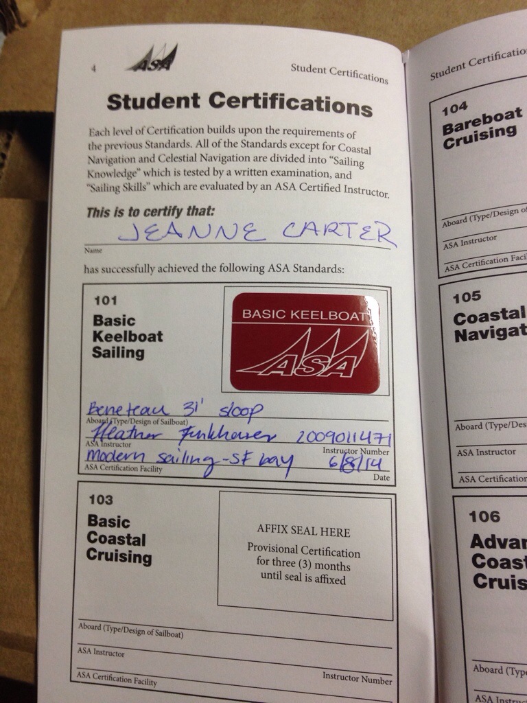
Who would have guessed? The Missus is the one Carter who actually went to sailing school and earned a keelboat certificate!

20140706-235042.jpg
Jeanne and friend Leslie Parsons attended Modern Sailing Academy in Sausalito, sporting handsome gear and scoring 94 of 100 on the written exam (to make Arlene proud, right?). Ted and Valda took us out on the Catalina today and the new drivers spent long stints at the helm learning SF Bay currents around Angel Island.

Back in the shop we had a good visit with Geoff who was down from Puget Sound. I saw photos of the 60′ tri he built – wow – and we traded tips and ideas. Makes me eager to learn more about the Wallas diesel stovetops, to pair that fuel source with the diesel furnace/water heater we bought a while back. Still looking for someone who’s actually cooked on one of these Wallas stoves. Also thinking of skipping an oven which could really improve the galley layout. Maybe carry a solar oven when cruising.

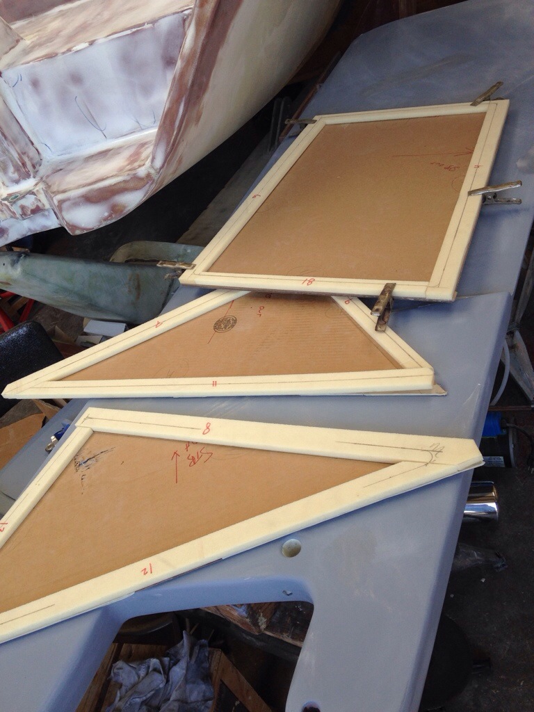
So not only is Jeanne exciting her husband by driving the boat, she came in to the shop yesterday and admired her new daggerboard. It’s in paint steps now; pretty great to have a big important part all done, and very rewarding to not have paid the $4k estimate to have one built for us (although we do have a solid $500+ in supplies in it).

20140707-000241.jpg

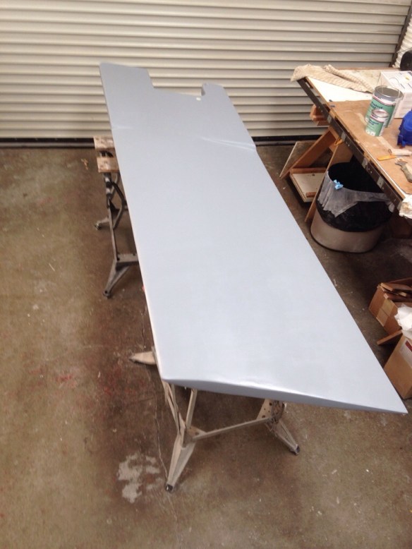
Not having labor bills helps get the mind ok with ‘splurging’ on the good stuff in materials. And with all the time put in the dagger, there’s no way I’d use anything but the best possible primer to permanently epoxy encase and prevent water intrusion to the glass or wood.

20140707-000532.jpg

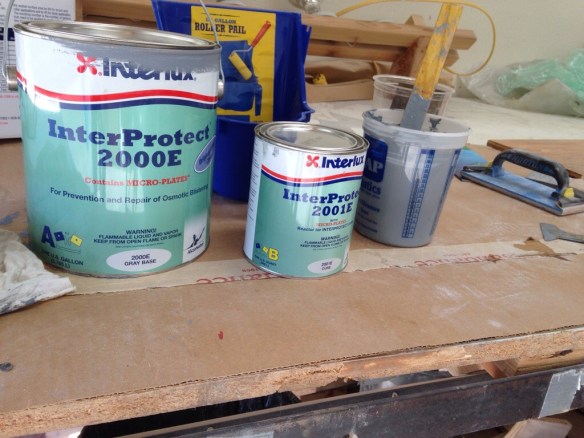
This interlux two part system is designed to sit under the two part LPU topsides and hard-style bottom paints. The primer claims a unique overlapping stacking system that forms tiny continuous barriers like shingles sloping down a roof until the waters flows over the edge. At $119 a gallon, we better not have to see the dagger’s primer layer for a long time (never, ideally!)

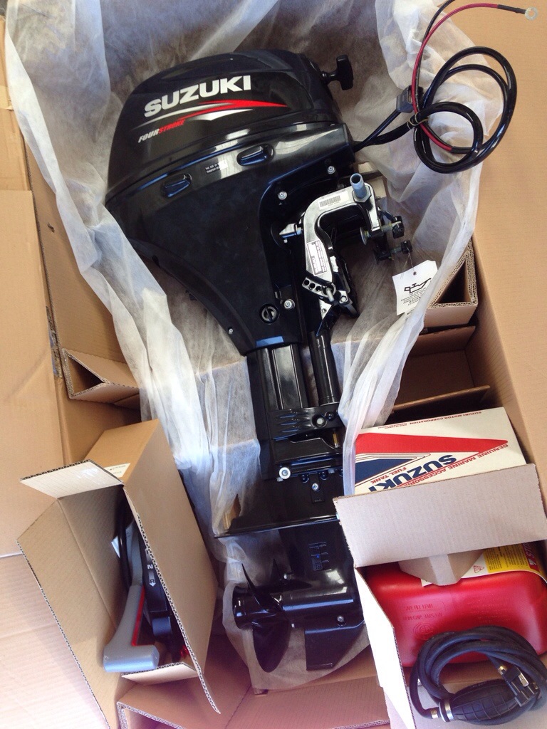
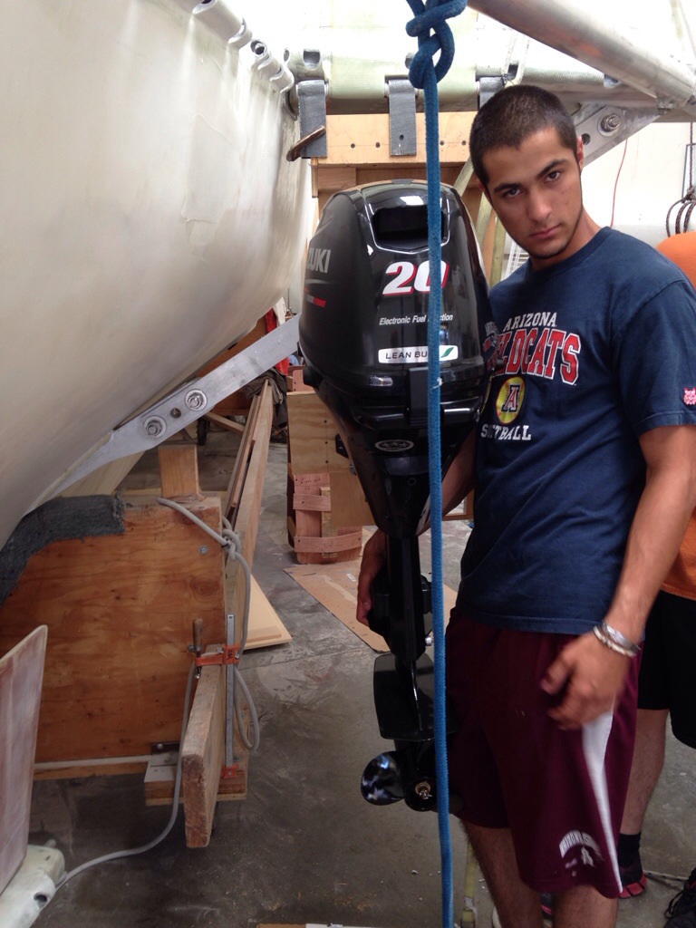
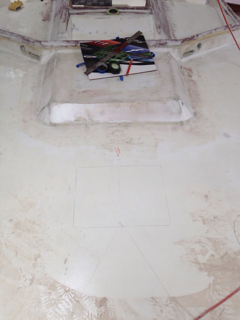
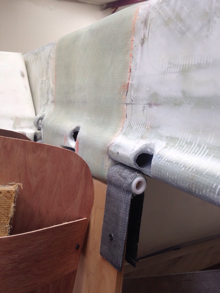
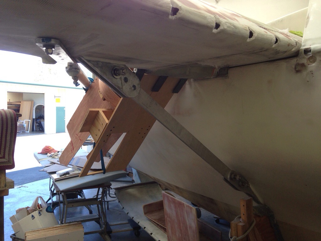
A big thanks here to Colin for repositioning the main hull yesterday in the hot afternoon and hoisting the port aft beam back in place on the boat so we can build the outboard motor mounting system. Next step is to either get the shell of a 20″ shaft old outboard or get measurements online and make a faux motor shape. I’m noodling over the swing-up brackets attachment points to the back of the beam. It’s all a little trickier than popping the motor on the transom of an F31, but in the end I think we’ll really appreciate having the motor tucked 5′ farther forward, pushing right on the heavy beam structure. Anyone with ideas / cautions, send them thru!
Thanks