Swing away motor

The F36 plans call for a traditional inboard diesel engine and propeller shaft thru the bottom of the boat. We can’t do a sail drive because we want the boat to be able to sit on its hulls in zero water, as in the extreme tides of Baja or England. So… Here we go “off plan”, switching to an outboard engine on a swing-up mount on the back of the starboard beam. I’ve been thinking up an approach that is both temporary and long term; if we don’t like the outboard the entire mount can be easily removed with only 1lb of hinges left behind and the trampoline put back in the engine’s place. Or when a cost-effective electric pod drive solution becomes available we can switch over. Or if an inboard diesel is really the answer, that can be retrofitted at any future time.

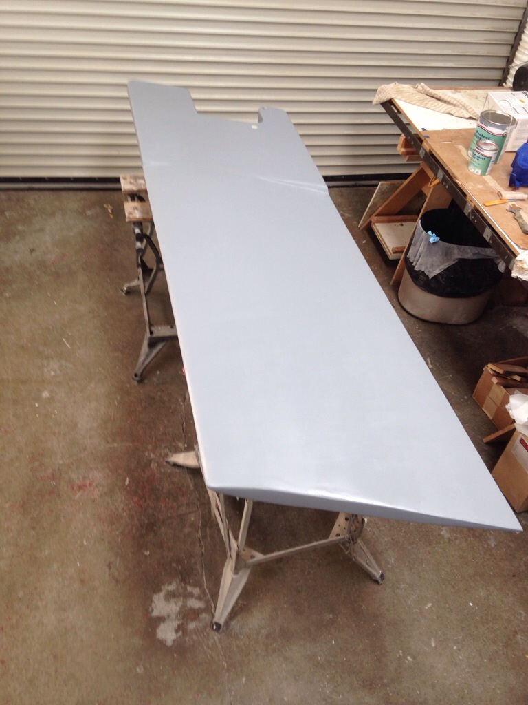
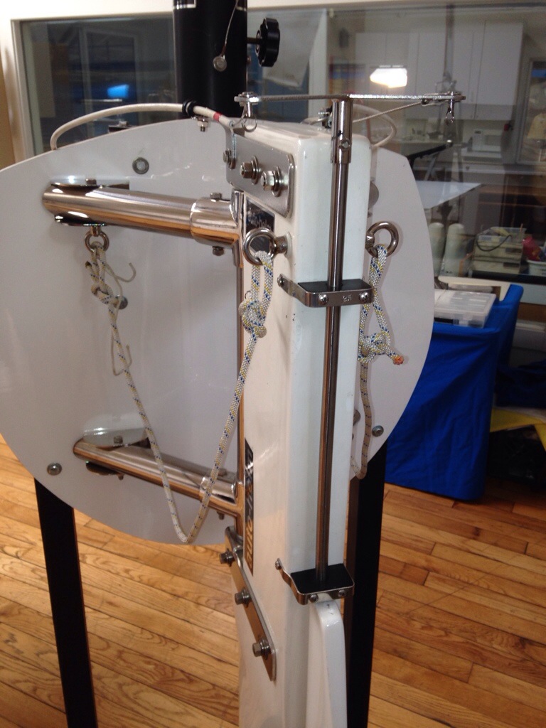
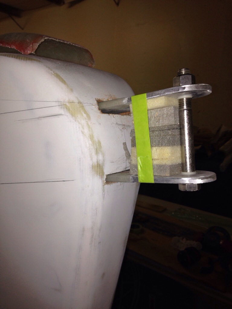
The measurements for a Yamaha 25 long shaft were found online and we made a faux motor of Luan door skins to practice with placement. The net lashings tube almost looks like a motor mount hinge, but it’s not parallel to the waterline and it wasn’t built to the shear forces and weight of the motor. So we need to work around that feature, and not cut it off the boat. The rudder gudgeons seem like a good model for the motor mount hinges and we have some spare G10 tube and a 16″ piece of 1/2″ stainless steel rod that will make a nice hinge pin with the right bushings in place. First up is fabricating the hinges.

20140715-221006.jpg

The funny shapes of the two pieces are what fit over the net lashing tubes on the beam. The other three will run on the top tab of the motor mount (yellow board is a stand in to see how this is going to work). I’m thinking the motor should be mounted as close to the hull as possible, as the hull shape curves away considerably down by the waterline. The weight should be tucked in close there, and things like the freezer and galley on the port side should counter balance this engine placement.

20140715-221518.jpg
We’ll pick this project back up next week once the bushings are in hand so we can align all the hinges and permanently affix the two big ones to the beam (instead of that blue tape :)
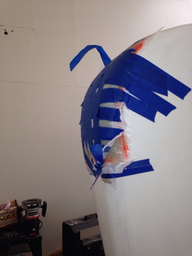
Thinking we’ll want to wrap them at least 18″ around the beam in both directions with heavy weight uni-directional cloth.
PS – the mounting box will be made to push up against the big diagonal brace under the beam, so the motor forces are spread out on a couple of surfaces, not just the hinge pin.

A license to Sail

Who would have guessed? The Missus is the one Carter who actually went to sailing school and earned a keelboat certificate!

20140706-235042.jpg
Jeanne and friend Leslie Parsons attended Modern Sailing Academy in Sausalito, sporting handsome gear and scoring 94 of 100 on the written exam (to make Arlene proud, right?). Ted and Valda took us out on the Catalina today and the new drivers spent long stints at the helm learning SF Bay currents around Angel Island.

Back in the shop we had a good visit with Geoff who was down from Puget Sound. I saw photos of the 60′ tri he built – wow – and we traded tips and ideas. Makes me eager to learn more about the Wallas diesel stovetops, to pair that fuel source with the diesel furnace/water heater we bought a while back. Still looking for someone who’s actually cooked on one of these Wallas stoves. Also thinking of skipping an oven which could really improve the galley layout. Maybe carry a solar oven when cruising.

So not only is Jeanne exciting her husband by driving the boat, she came in to the shop yesterday and admired her new daggerboard. It’s in paint steps now; pretty great to have a big important part all done, and very rewarding to not have paid the $4k estimate to have one built for us (although we do have a solid $500+ in supplies in it).

20140707-000241.jpg

Not having labor bills helps get the mind ok with ‘splurging’ on the good stuff in materials. And with all the time put in the dagger, there’s no way I’d use anything but the best possible primer to permanently epoxy encase and prevent water intrusion to the glass or wood.

20140707-000532.jpg

This interlux two part system is designed to sit under the two part LPU topsides and hard-style bottom paints. The primer claims a unique overlapping stacking system that forms tiny continuous barriers like shingles sloping down a roof until the waters flows over the edge. At $119 a gallon, we better not have to see the dagger’s primer layer for a long time (never, ideally!)

A big thanks here to Colin for repositioning the main hull yesterday in the hot afternoon and hoisting the port aft beam back in place on the boat so we can build the outboard motor mounting system. Next step is to either get the shell of a 20″ shaft old outboard or get measurements online and make a faux motor shape. I’m noodling over the swing-up brackets attachment points to the back of the beam. It’s all a little trickier than popping the motor on the transom of an F31, but in the end I think we’ll really appreciate having the motor tucked 5′ farther forward, pushing right on the heavy beam structure. Anyone with ideas / cautions, send them thru!
Thanks

100 holes

I wrote some time back about not wanting a couple hundred holes in the hull for little bolts to hold the trampoline net lashing eyes. But it was surprising how many hours – close to 100 – went in to affixing, fairing in, and hole-notching these 48 attachment points for the nets along each side. And of course the same thing was done on both sides of all four beams, with the float decks still to get theirs. This is one of those tasks that gets a single paragraph and small drawing in the plans but will have taken us a month in labor hours all-in. Yikes

20140629-222234.jpg
Here’s how it looked after drilling holes 3/4 thru from the top then finishing the hole upwards via the pilot hole extending thru the 1″ hollow hole saw. This hourglass shape then needed to be cut on the perpendicular using the multi-tool saw blade. The point is to get a Vee shape so the lashing lines can enter and exit the tubes at 45 degree angles. The lines will wrap around a skinny fiberglass rod placed inside the tube.

20140629-222718.jpg

We took a break today and visited the Master Mariner’s wooden boat show at the Corinthian in Tiburon. Colin, Jeanne and I each had different favorites. Origami raced against Yucca many times, and getting to meet Hank Easom aboard his lovely, fast war machine was great. We toured Eros, the 105′ schooner rebuilt by a marvelous couple through their 60’s and 70’s, and now touring the Western Hemisphere. Jeanne wants a light prism in our boat, just like big Eros’ cabins.

20140629-223220.jpg

Perhaps the best part was meeting the owners and seeing the pride they take in caretaking their ships made of wood.
And I think we’ll lift an idea right off the oldest active sailboat in California. The Spaulding Wooden Boat center has just relaunched Freda after an 8 year rebuild – those volunteers and staff took the entire boat apart to repair extensive damage/rot.

20140629-223744.jpg
The ah-ha was seeing the cabin top grab rails. I’ve been fretting over needing them but not wanting another bulky looking element on deck…

20140629-223952.jpg
Thinking the modern version of these things on Freda would be sleek carbon anchors every three feet and some nice grey no stretch dyneema line. Thinking about it, anyway.

But the best part of the day was watching Mrs. Carter take the helm as we went out sailing this afternoon, and show Colin and I what she had learned in her May/June ASA sailing course. The bay kicked up a steady 20kt wind, 5 big cargo ships, 4 ferries and a LOT of sailboat traffic to mess with the driver, but she plowed ahead like a champ. Practice makes perfect, so we’ll be bugging Dad to get the Catalina30 out more often :). Go Jeanne!

Back to work

Well, the contract work and family healthcare issues have consumed June’s workshop hours. Did manage to sneak in a few hours for fairing work here and there. And on Victoria Day in Canada, the intrepid Stephen Marcoe picked up our mast near Toronto and headed west. The stick is close now, about 250 miles away in northern Cal. Stay tuned for more on that. And for those who are smart enough to buy a finished boat, Stephen has a great one up on eBay right now. Check out the Contour 34 Trio listing.

20140627-141156.jpg

This is the finished product of the spinnaker pole mounting base. The big aluminum tangs extend four inches in to the bow with a bunch of reinforcement webs in there. I think I’ll make the pole out of carbon instead of the original aluminum plans.

The daggerboard is finally done and it was a great way to really learn proper longboard fairing. That exercise should make the below-the-waterline hull fairing go much better. Board photos will come after some primer is applied this weekend. We’re quite happy with the final shaping.

It’s good to be back at the boat work. Onward and upward towards the launch.

Shiny bits

Today was a trip to the east bay to pick up the self-steering vane from ScanMar in Richmond. The wind vane component will get mounted atop a new arch at the back of the boat, and the white cables in the photo here are what connect the pendulum vane to a trim tab on the back of the rudder. I didn’t photo enough of the air vane at the top to get a complete picture, but this is just the start of this story.

20140527-230956.jpg

20140527-231011.jpg
In the second photo, see the stainless rod that serves as the hinge pin for the trim tab. On this display model, everything is external and not particularly hydro-dynamic high performance. So the next stop today was a visit to the design studio of Jim Antrim with our rudder in hand. He will draw up a recommendation for cutting the rudder to make part of the trailing edge the trim tab. Rick Holway will be glad to know that Jim designed a similar modification to the big local tri Defiance’s rudder; it was exciting to have him pull up those build plans on his computer today. That project was tricky as the control rods had to run up through the rudder post (because it’s under-the-boat rudder) Ours won’t be that intricate because it’s external, but we still have considerable work to build internal bearings and a carbon hinge running from top to bottom. Lots more to come on this topic over the next month.

And here was a very satisfying spend at the Oakland boat show. With the myriad choices out there for sailing hardware, I decided to (1) go with stainless steel to match our shiny Anderson winches and (2) buy local. The Garhauer company in Upland, CA were original suppliers to Corsair, and F27 Origami still has most of her 23yr old Garhauer gear working well. This is a family business doing their own manufacturing, and I spent an hour in their boat show booth picking out this loot:

20140527-232806.jpg
This is most of the sail handling gear, plus the anchor roller and the solid stainless steel forestay chainplate. The rest will come from Colligo, in conjunction with all the synthetic standing rigging (no wires).
It’s fun to see how big this stuff is compared to our prior boats. The jib cars are the size of decent hamburgers! And that’s a big size 52 winch in the photo.

20140527-233707.jpg

Almost ready to show you final photos of the daggerboard and hull-side net lashings, but there’s still just a bit more filling and sanding to do. Apparently the entire Memorial Day weekend wasn’t enough :)

Breaking radio silence

005 is back on the airwaves tonight after a busy month outside the boat shop. Some family health issues and the builder’s pursuit of the legal tender cut the boat hours way back. But now Mom’s leg is healing and the contract work with a friend’s company is sorted out. We need encouraging thoughts beamed towards Ontario, Canada on Tuesday morning as Stephen Marcoe pulls a Formula 30 cat on its trailer to the shop where our mast sits waiting near Toronto. Hoping to get two masts on the trailer that’s only expecting one, and get that long drive west started right away. It’s been two years of snafus in getting this 50′ stick “out of the mud” and I’m very anxious to show you photographic proof it’s been matched up to its boat in California! Stay tuned.

The daggerboard glassing and fairing has been attacked in little windows between trips to the hospital, etc. The whole project isn’t taking too many hours (maybe 30 ish?) but it’s going to be two months on the calendar this spring. One side is all ready for paint:

20140519-235238.jpg
And the other got a thick layer of fairing compound just after this photo. Finished board seems to be about 100 lbs. I can JUST flip it over and move it around the shop alone.

Another small steps project done is the mounting base for the bow sprit pole. Again, we take a perfectly nice boat hull and put two nasty cuts right out front.

20140519-235852.jpg

Before those cuts comes the molding-on of glass to make this bow cap. Mold release helped the unit pop right off when dried.

20140520-000132.jpg

20140520-000156.jpg
Here are the three fabricated parts ready to install…

20140520-000259.jpg
And with the slices in the cap, a potential Halloween costume.

20140520-000348.jpg

The cap got cemented on and the tangs glassed inside the bow forward chamber. Will get some shots during fairing, but this should be a great anchor point for the screacher/Drifter.

Today’s work (and recent past) is fairing in the net lashing tubes along the hull. Andy Miller warned this is tricky, and I hope these come out much better than the metal eye straps screwed in everywhere on older boats.
We’ll get photos when it all looks decent.

And wait till you see all the boat jewels acquired at the Garhauer booth inside the Oakland boat show. Spent an hour in there and came out with the entire package of sailing hardware. Two grand in stainless steel, strong and nicely paired with the 5 big Anderson winches awaiting their mounts. Gotta fair and paint prep first!

Is that the keel?

Hi folks – sorry for the time gap as I had some software troubles with the latest WordPress update. Plenty has happened on 005. For example, just when I thought the rudder was done, the conversation at the boat show with the founder of ScanMar self-steering systems led to purchasing an AutoHelm wind vane that will steer a trim tab on the trailing edge of the rudder (think of the flaps on the airplane wing). Haven’t heard of anyone who has done this yet with a Farrier cassette rudder system, so I’ve engaged Jim Antrim, a SF Bay Area naval architect, to design the modifications I’ll need to keep a working foil shape. Stay tuned on that story, after the first meeting with Jim.

20140418-234148.jpg

So, the ‘keel’ – most visitors to the shop ask how the boat can be sitting close to the floor, “where’s that big fin that sticks under a sailboat?” Then we have the conversation about the 100,000 lbs of buoyancy from the leeward float and we look at the big slot in the bottom (and top) of the hull. Well that big hole is almost plugged with the new retractable daggerboard. It started life as these western red cedar 2×8″x10′ planks that we’re milled about 25 years ago.

20140418-234620.jpg
Since the dagger trunk is already installed, we cannot build the daggerboard too thick such that it sticks or jams going up and down. The plans warn to make it smallish and later on use shims to take out any sloppy movement. So we calculated a 2.5″ thick wood core was needed before the fiberglass work. So that led to planing the planks down to 1.25″ each…

20140418-234939.jpg
There’s a big thanks to neighbor Michael for the hour we spent using his big planer. Our machine would have taken much more work, plus his magic sawdust collection system made it all disappear!
Now the planks get arranged for glueing up – 80 board feet of 8″ cedar was a pretty big load!

20140418-235244.jpg

20140418-235314.jpg
This job didn’t get a full size plan and tracings as the dagger is one consistent for-aft size and built on parallel lines. So we just traced it all out right on the wood.

20140418-235600.jpg

Now for the underwater shape – that comes from a full size drawing in the plans, and we took depth measurements at set intervals along the curve, just as was done building the rudder last month.

20140418-235825.jpg
On the first side we started with the router,but the huge amount of material to remove proved daunting. So we switched technique mid stream, and I’d say this is the way one should try: set a good circular saw to the contour line depth that follows a straight line, and run the circ saw to cut that groove. Repeat for all the depths needed to create 1/8″ depth steps. 1/16 would be better, but my big worm drive saw couldn’t be set that precisely. Then we cleaned out the cuts with blown air and spray painted to get dark lines at the trough bottoms.

20140419-000419.jpg now it’s relatively easy with the power hand planer to shave down the board until getting close to the spray paint lines. And we found the final shape with the ShurForm.

20140419-000622.jpg
Next up was rebating out more wood to make 10″ wide carbon fiber stiffeners down each side. Our original football field worth of unidirectional carbon rolls is now down to a single first down’s worth.

20140419-000924.jpg

20140419-001051.jpg
The plastic pipe segments near the top of the board are where the pull up and pull down ropes will be attached.
And actually, before the carbon went on, the cedar was cut through to refill with a hardwood insert of maple at the intersection of the waterline below the boat and the board’s midpoint.

20140419-002026.jpg

20140419-002102.jpg

The fiberglass skin is now applied, except for wrapping and vac bagging the board’s edges tomorrow. More photos in a few days when it starts to look good. It’s sized like a barn door, a tad over 8′ long. Gonna take a couple of us to wrangle it up on deck for trial fitting!

Rinse and repeat

After the task of laminating all the net lashing tubes shown on the prior posting, it was on to the same for the starboard side. We did the primary work in one long day; three separate vac bag applications needing a couple hours each, plus all the materials prep time in between, all took about ten hours. Overall, these hull-mounted net attachments are looking like a solid 40 hour week of work. Drilling and installing a few hundred screws and eye straps would have been much quicker, but I have no interest in all that steel / rust and potential for little leaks all around the boat.

20140402-084024.jpg

A coat of primer goes on the rudder today while we look for wax or vinyl sheets to use as a release agent around the rudder to start building the cassette. (Any rudder builders out there have a suggestion?)

Go Brandon Belt – very good to have baseball back on the radio to fill the shop in the evenings.

Be a better bagger

It’s too bad they don’t teach this stuff in high school; no idea where one can get a hands-in education in vacuum lamination techniques. Things are being done safely here in the shop thanks to book and video study. But it’s all the little tricks not known that cause extra time and sometimes rework (go back a few posts to the vacuum pump saga :)
This week I think we’ve finally gotten in the groove, so in case anyone reading this stuff is just starting out, maybe these musings can help reduce some error in your trials?

20140327-224422.jpg
That’s the second of four stages vacuum laminating the net lashing tubes to the hull’s port side. Significant only because it’s the first success using a splitter to draw vacuum on two separate projects in one pump run. A small moral victory around here.

Stage 3 was the 15 foot section between the main beams. Here are the steps.
Took measurements between the temporary straps, and cut all materials to leave an inch and a half on both sides of the straps so epoxy wouldn’t migrate over the straps.
Built the bag down on the 8′ work table where it can be stretched snugly and the sticky goo tape applied, leaving the paper backing in place. Setting up the tape in this calm manner, before any epoxy is mixed, took me too long to realize!
Planned for add-on patches to make out-of-the-way zones in the bag for the pump fittings to sit. Leaving at least six inches between the air connection and any live epoxy work, linked by plenty of breather fabric, keeps the glue away from the pump’s tubes and fittings. (Learned after a nasty hour of scraping out glue-fouled bag fittings one night – these parts aren’t a quick Home Depot replacement).
After cutting fglass fabric to the six inch width for this job, the ‘bagging’ supplies were cut: peel ply at 7 inches because a bit of overlap makes it MUCH easier to remove later, release film at 6″ because any more would be waste, breather fluff at 5.5″ because when it goes all the way to the edges it invariably ends up adhered where you don’t want it, like on the hull!, and the bag film itself at 11″ – leaving 2-3″ past the edge of fiberglass is minimum. For this vertical work I needed the bag to help hold the wet materials in place before the pump turned on, so I cut it close and snug on purpose.
With materials all ready, it was time to apply the putty fillet around the pipe, and let it harden up a bit, but still pliable for the bag to press the fiberglass into the fillet and be able to take by-hand smoothing from the outside of the vac bag.

Here’s the bag in place, but folded down out of the way.

20140327-230235.jpg
Then the fglass was wetted out on the table and rolled up like little pillsbury crescent rolls (sans hot dogs, Mom) and walked over to the boat after sitting under warming lights for about 20 mins to get tacky (sticky). Here that is with peel ply to help hold it up. Note that it won’t adhere yet to the underside – gravity wins.

20140327-230616.jpg
The heat lamps are going because there is a putty fillet above and below the pipe, trying to time it so that is just hardening when the vacuum is applied. Too early and it will squish out; too late and there will be ugly lumps in your cream of wheat.
Next shot is after applying release film and breather fluff, some of which needed dabs of masking tape to hold in place. Bag was then brought up over the work taking care to tuck things in flatly.

20140327-231013.jpg
With this long, complicated bag, there were some air leaks but they were solved in a few minutes by pressing the tape all over again and adding a few inches of backup here and there. Having these separated tube attachment areas has helped quite a bit, compared to earlier work where I didn’t plan out the connection spots. Cut the bag to fit the work, and simply add a big ‘patch’ as needed.

20140327-231414.jpg

All in all, no drama today and it all came out with nice, uniform tubes that need only minor fairing work. In retrospect, I probably did this all backwards; someone could try small 2-3″ fiberglass strips next to the pipe straps first. Then remove the straps after the glass strips dry, and you could probably do the whole project in fewer bagging sessions. Just a thought.

And as Jeanne’s Mom always said when preparing the fruit for canning, “I found the one we’re looking for – the last one”…. Here’s beam number four escaping the oven. Don’t ask about the electric bill. This big box is REALLY in the way, but it will stay up another day or so to bake the rudder after the last fairing work. Getting excited to start on the rudder’s cassette steering assembly!

20140327-232242.jpg

Borrowed from the Missus

20140323-232805.jpg
It’s actually hard to find a remote-sensing thermometer that will read warmer than your average bad day in Death Valley. This one from Home Depot tops out at 158 degrees, which works for our 160 target. The ‘oven’ has a removable section of Sheetrock to reach the power switch and read the old fashioned meat-cooking thermo inside to make sure we don’t get a runaway thermal event past 175 degrees or so. This combination does the trick. We also had to hard-wire some temporary plugs, conduit and switches because regular power strips couldn’t take the heat or current draw. Also needed to find a replacement air circulation fan after smashing Colin’s nice little unit with a little slip – oops. The fan is a must with a box this big – think of how convection ovens have hit the home improvement market.
Too many trips to the hardware store and wasted time on various improvements, but this post-curing system is now a-ok. Beam #2 was cured on Sunday, and the other two will fire early this week.

Meanwhile, the net lashing anchors are going on the main hull, similar to how it was done on the beams. Step 1 was temporary strapping of the PVC to the boat – it makes a nice clean line all along the gunwale …

20140323-233705.jpg
We’ll laminate the fiberglass in sections, skipping the spots where the pipe straps sit. Once the primary bagging is done, we can hand-patch the little spots left in between. The straps are held with tiny 1/2″ screws, in just enough to bite. Those little holes will get putty filled before we proceed to seal everything up.

Sunday afternoon was spent preparing the 186′ of six-inch wide 18oz fglass fabric needed to create these lashing anchors. That’s 31′ along the hull x three layers x port/starboard, plus all the vac bagging materials. After ten minutes of scissor-burning wrist work, it was a run back home to grab Jeanne’s fabric cutting board and rotary cutting wheel. That helped a bunch, and it was returned in time for tomorrow’s prom dress sewing.

20140323-234338.jpg

Rudder fairing is good – first side finished today, and we attempt to get the exact match with side two starting tomorrow. Just keeping things fair, man!