Beam-to-float sleeves underway

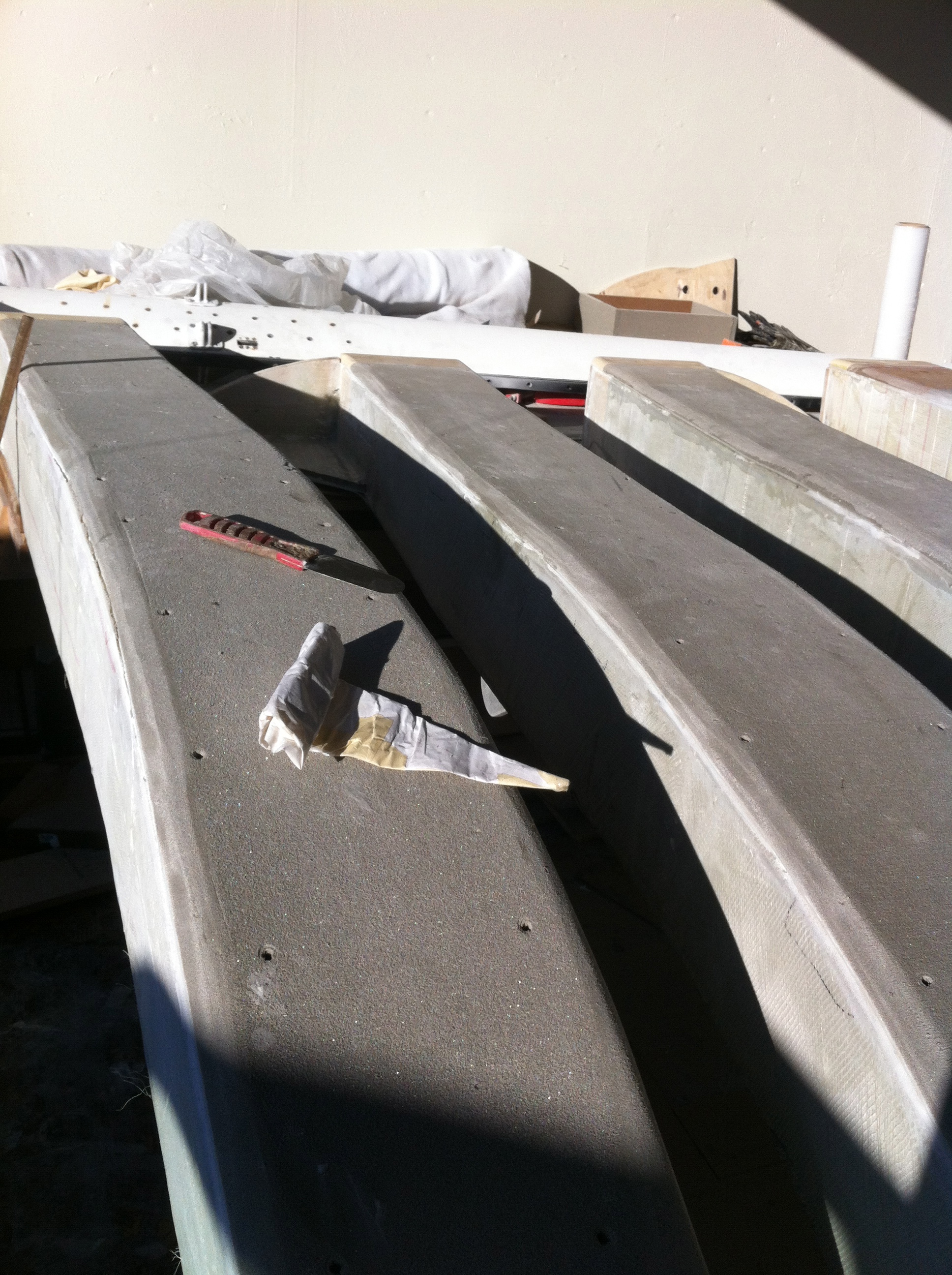
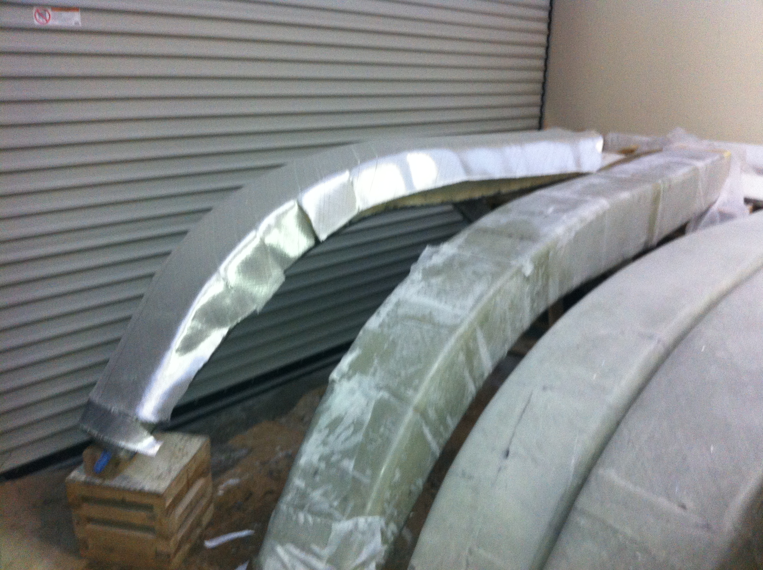
Now that the big beams are structurally complete, the outer ends serve as the molds for making receptacle ‘sleeves’ that will be mounted inside the floats. Since these sleeves are built exactly to the shapes of the individual beams, I now see how the beams get a perfect fit into the outer ends of the boat. Sounds easy, but the first sleeve-making was a nasty failure. Didn’t do enough mold-release prep, and the whole new 26″ long sleeve seized up around its beam and would not slide off. Ended up sawing it all away and damaging the beam finish. VERY frustrating and a loss of a couple days work.
So tonight was a happy moment when the second attempt version slid off as planned!

20130205-221733.jpg
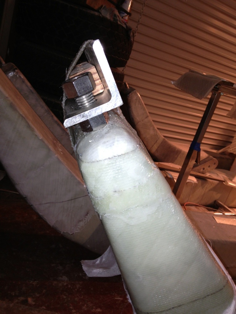
After the sawzall job, advice came in to test the slippery tape I had used – the cheap HarborFreight stuff turned out to ‘catch’ the epoxy, while some 3M tape had a better release. Lesson learned. Next up was adding a lot of mold release wax over the slippery tape. Helped a lot, but I’ll do another layer for the other sleeves. Third note was to glass on some blocks to the slides for hammer blows. Emotionally satisfying to smash away, but ineffective in causing the sleeve to actually budge. What worked was the brilliantly simple idea from IanF to lever off of the beam bolt. In the photo you see a nut and washer between the beam and a metal lever bar. The bar was temporarily glassed to the sleeve, but not the beam. It took about five full revs of the nut, and the whole sleeve finally released. I might be the last person on the planet to make F36 beams, but if any other builders read this, I’d warn that this lever idea is the only way to actually get these things to budge unless your beams are PERFECTLY shaped and faired. The compound curve and length of the forward sleeves is too much for simply sliding off the beam.
Anyway – it finally worked and what a huge relief!
The four fairings are built now, and after finishing up these sleeves, it’s time to put the whole thing together, starboard side first.

20130205-222651.jpg

20130205-222729.jpg
(These photos show sleeve 1 with only the initial two glass layers. Will move to the workbench to add two more glass layers, beef up the end and bed the heavy duty beam bolt washer, and grind away the temporary lever strap and pounding blocks)

Beam fairings underway

Here’s the first fairing planked in the mold. The bottom side of the fairing was done in one piece up to the sixth frame – that should make for a nice smooth underside. From there the foam planks were cut to the width of my big 3″ straightedge to make things fast and easy.

20130106-184724.jpg

After the inside is glassed and the fairing comes out of the mold, the foam core should take to the shaping tool quite well – I’m using a 12″ shurform and this foam files off easily. Will cut fabric and laminate tomorrow night.

20130106-185100.jpg

While Dad was in the shop last week we started mocking up options for the boat’s stern section. I’m leaning towards external steering linkage connected to the aft-cabin-top mounted tiller, so the tie rod would run just above a rear deck, shown here in yellow foam core. We need a step (box at left on the deck, and another one cut in to the aft cabin sloped rear wall. I like how the F39 Alice’s Restaurant (up in Puget Sound) handled the cut-in step. There would be a small lower deck for boarding, and mounting the swim ladder, surrounding the rudder mounting “post” structure in the middle of the photo. Engine exhaust would probably exit the hull near the stern, but outside the sloping hull lip on the starboard side. I want the exhaust far back, but I think not actually inside the transom scoop area. Hope to get some pros/cons advice on that…

20130106-190644.jpg

Beginning the beam fairings

The primary beams shown in prior posts are 10″ wide. Now we start on the fairings, or ‘caps’, that mount to the front sides of the beams. When complete they’re about two feet wide, which should be a good walkway between the hulls. The fairings will be strip-planked in female mold frames, in the same manner as the hulls. Except these will have lightweight foam core, not cedar.

20121229-222951.jpg
Step one is transferring the plans to the frame base. The curve of the beam is seen on the left side of the white paper. Carbon paper is laid underneath, and we simply trace over the pattern to mark the wood or foam core.

20121229-223420.jpg

Here are the form frames getting ready for mounting to the base and then planking can begin.

Christmas Greetings from the boat shop

Sane people were home wrapping Christmas presents. Here on the sailing fringes, we were wrapping with a special brand of itchy fabric :)

20121224-154706.jpg

Glassing the beams all the way around is a messy job, with epoxy dripping and catching on the clothes, etc. So it was a night to push through, and by 12:30am all four beams are now structurally complete – building them was pretty much a full year of work squeezed in amongst the full-time “day job”. Happy to move on to cosmetics.

Merry Christmas to you Royal Oakers, my colleagues, fellow FBoaters, dear family, Friends of Origami, and people humoring me by reading this stuff. May you enjoy a safe, happy holiday time. And if things go well, let’s sail this big boat together in late 2013!

20121224-155442.jpg

The one I was looking for

Just like peeling the last apple in the canning batch, we finally found the last piece of over a hundred layering sections for the beams. All of the bottom layers had to have two precise slots cut to fit around the brace tangs.

20121221-225521.jpg

The forward beams have their final 14 layers done with progressively shorter staggers measured so that the thickest lamination is centered over the brace tang.

20121221-230752.jpg

Similarly the bottom faces got 10 more layers on the forwards and 4 on the afts.

20121221-231005.jpg

Tomorrow I’ll add the reinforcing patches at the high stress points, then the complete beams get wrapped in two layers of fiberglass.

1 & 1/3 football fields of black gold

Finally, the beam work arrived at the satisfying step of laying down large tracks of carbon fiber! Listened to the 49er’s game on the radio while rolling out an entire football field’s worth of laminates this afternoon. After a busy weekend, all beams now have six layers of carbon on both their top and bottom sides. That’s it for the bottoms. Next weekend it’s 14 more layers for each of the forward beams, and a lesser amount for the aft beams. Watching the $500 rolls of carbon whirl away is a bit like the depressing feeling at the gas pump when fueling up a Suburban. Gulp. The beams are getting quite heavy, but still possible, for single handing. The fitting into the floats will certainly take two people and some jacks. But that’s still a ways off.

Trying to decide the sizing of the aft cabin – to – cockpit hatch. 24″ square is too big. A 20″ unit seems just big enough for shoulders access, but will mean cutting away more cabin roof than already done. Glad I experimented with various sizes in cardboard this weekend. Now it’s keeping an eye on the clearance page at Defender – seems to be the best place for good deals.

20121202-182612.jpg

Installing the beam caps

Too long between posts!  It’s probably due to too much work travel, and the beam work has been repetitive steps of not very interesting stuff. The mold for the beam caps was easy – the shape was formed from having saved the off-cuts of the sheets that formed the beam molds months ago.

Image

We elected Dad as the ranger of the clamp forest; figured he earned the title based on who had more epoxy on his shirt :)  The beam caps went on without too much fuss, and we used PLENTY of epoxy putty along all the horizontal surfaces at the tops of the beam structures.  With the caps on, these now start to look like substantial beams!  And a shout out to Mike Leneman’s grandpa – notice the squeezed out tube in the photo below. That’s a magazine cover rolled up like a cake decorator’s bag. Roll the paper spirally, tape the seam, fill with putty from the top, roll the top closed like toothpaste, and cut the desired bead-size hole in the tip. This idea is working GREAT for filleting. Thank you Mike!

Image

And now the past couple of shop days have been spent wrapping the beams in 2 layers of DB170 fabric. These beasts are growing heavier with each step, but I can still push them around and roll them over enough to make progress solo. After finishing this evening, there’s just one more step of wrapping the ends (after repositioning the supports), then we’re ready for laminating on the black gold – 16 layers of carbon for the tops of the forward beams. Actually looking forward to that job – very satisfying to be using space-age material for a strong, light boat.

Image

the two on the right were done last weekend – curvature of the beams makes the fabric shaping very difficult, so I’m resigned to overlaps for strength, then sanding and fairing as needed. Beam in the middle had just been finished and peel-ply’d, and the last one is shown ready for the evening’s epoxy job.

Thanksgiving weekend sounds like a good time to get started on the beam fairings mold, and hopefully those structures will be built much faster than the core beams.  I won’t be installing the plan’s aluminum backing strips for the net lashing eye strap screws – we’ll be doing the updated ‘slit-tubes’ as seen on this F39 beam:

Port beams trial fit

Thanks to Griffin for lifting the port beams up in to position (I can see why other builders hoist completed floats up out of the way!). Good news is these beams lined up just fine. Labor Day weekend is slated for installing the diagonal bracing tangs in to the beams. These two beams’ internals should go much faster than the starboards because all the parts were fabricated at once, so this time it’s just an install job.

Access to one of the forward port beam bolts is inside the shower stall wall, so that led to deciding/cutting in a cabinet door – that’s going to be a great storage space for bulky bathroom things. The shower stall is generous – might use up some space with a vertical water tank? Time to calculate the volume of 6″ deep, two feet wide and five or so feet tall. Hmmmm

20120827-132818.jpg