Boarding platform

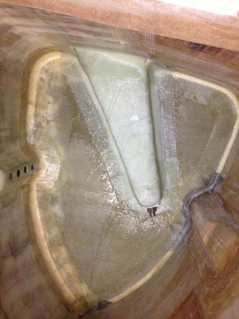
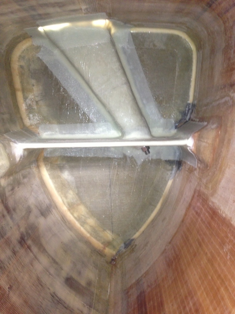
The stern area of the boat is mostly worked out now, with the ‘back deck’ and swim step all tied structurally to the rudder post. The port side will be for climbing aboard, so the lower platform is extended a bit past the hull edge to make a proper foot landing pad. A ladder can be bolted to the vertical panel above that step.
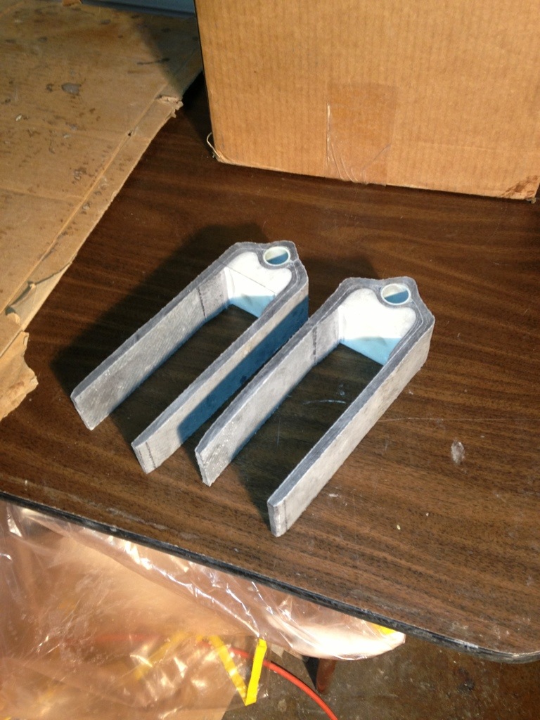
The red color comes from the ‘microballons’ – fine powder that thickens the epoxy and makes it sandable for final smoothing. These red lines in the corners are the ‘fillets’ – curved joints of glue that significantly increase the surface area (thus strength) of the bond. The gentle curve also makes the fiberglass tape layer (still to do in this photo) adhere better.

20130331-161714.jpg

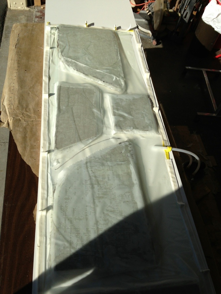
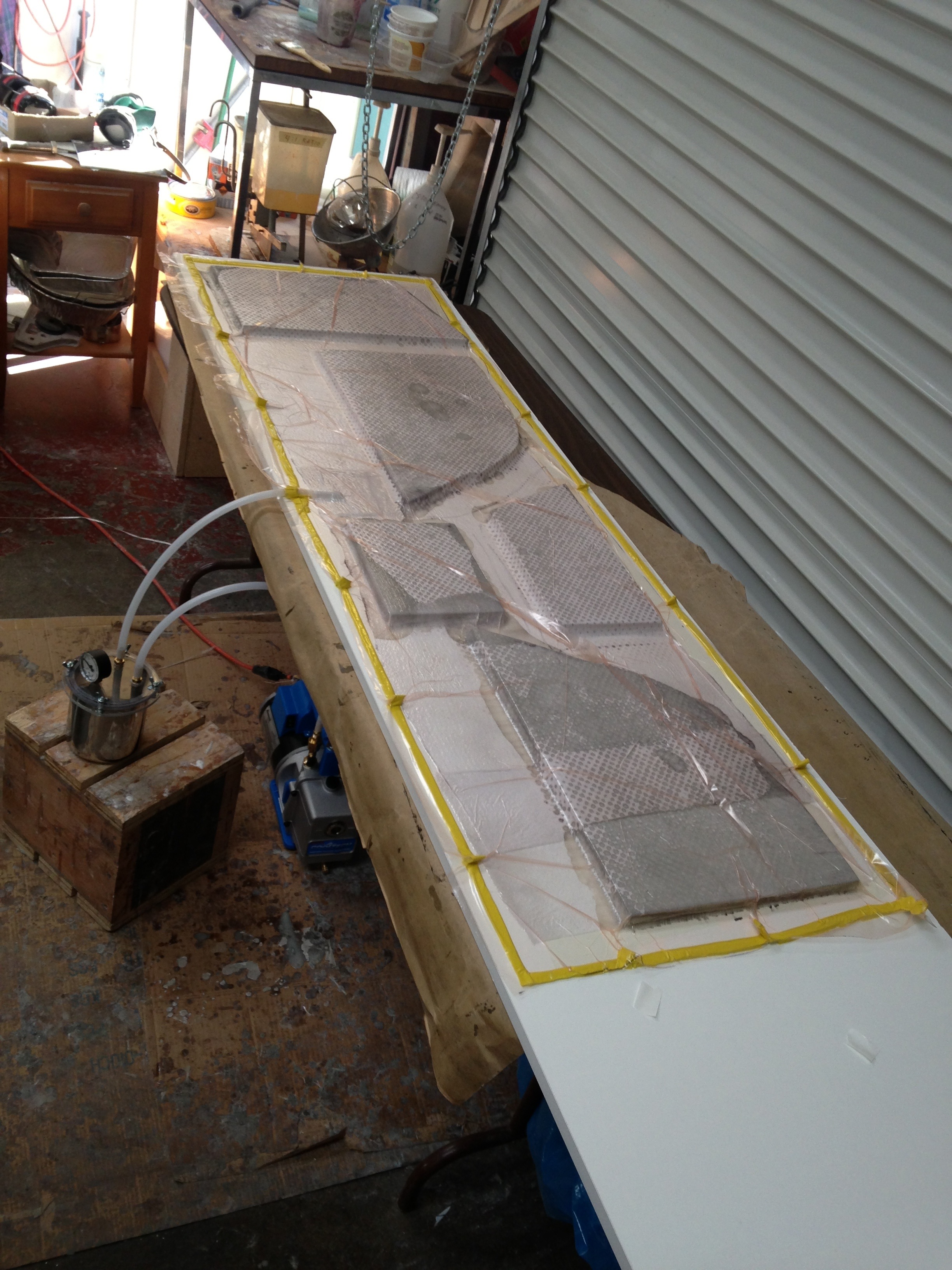
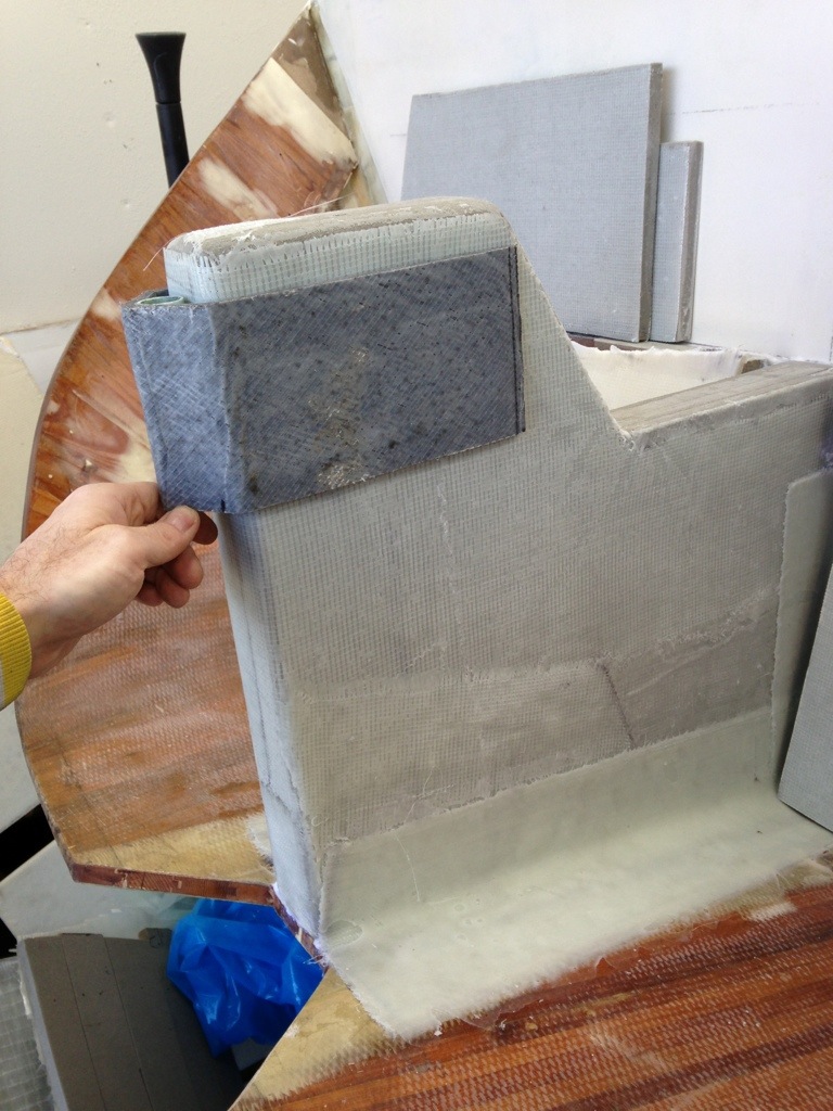
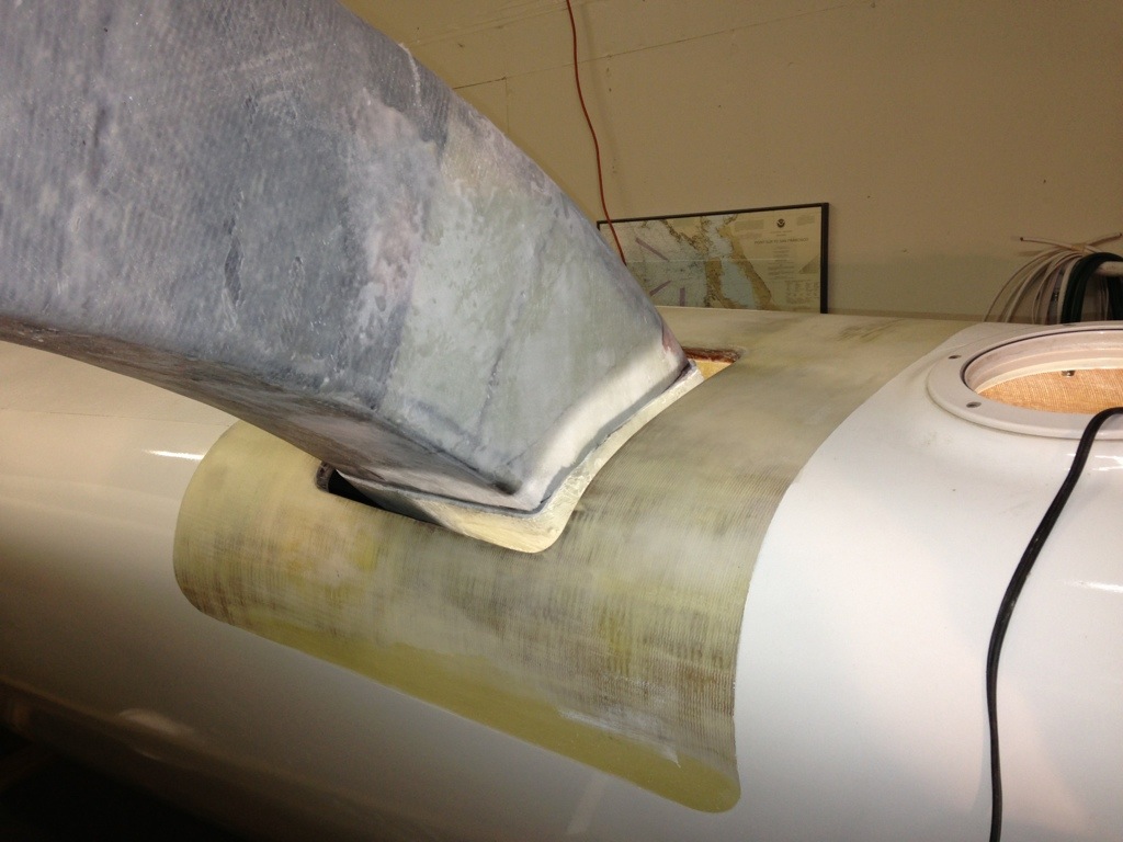
Also worked this weekend on affixing the beam fairings to the fronts of the beams. Cut three access holes in the tops to reach inside and tape the inside surfaces to the beam and float. This photo is the start of bolting flanges. Glass is affixed to the beam but not the deck (plastic tape and wax in between. All of this will look much prettier after the beam comes back off and can be worked down on the floor. Stay tuned…

20130331-162222.jpg

Rudder gudgeons and beam fairings

Here are the rudder gudgeons installed. The camera angle makes the lower one look tilted, but the silver rod has the pair plumb and aligned for the rudder. Ordered 8 fancy bushings needed; they will be pressed in to that green G10 fiberglass tube seen in the gudgeon-build photos.
The whole aft scoop area is getting tied together structurally, including 5 layers of 18oz BD glass in the gudgeon area – I went a little beefier here than the F39 plans, deciding that a couple more pounds would make us more assured in a storm some day.

20130320-235917.jpg

The starboard side looks better now with the beam fairings in place. This final shape is much better looking than just the square box beam.

20130321-000134.jpg

Finished gudgeons

A short post here to show the gudgeons completed and ready for alignment and bonding to the steering base area. I need to find a straight, 7/8″ rod (maybe just a good dowel) to get them plumb with each other before cementing in place. Once that’s done, the whole back end can get built out. Should be a busy Saturday in the shop…

20130314-215543.jpg

First step in the steering syst

Started work today on the rudder and steering system, and it was very sobering to fabricate the gudgeons (pivot point for the whole rudder) after reading this morning about the Columbia 30 race boat Uncontrollable Urge losing her rudder and crashing on Sam Clemente Island. It reinforced the idea of doing the very best possible laminating work of these parts. The piece in the photos is actually the pair of gudgeons being built as a whole, and to finish it will be ripped into two separate pieces. It started as a foam form with a piece of G10 fiberglass tube, then 16 layers of carbon fiber. Later today, I added ten more carbon layers wrapping the exposed side of the tube in between the legs.

20130310-220154.jpg

When they’re done, the fit over the rear post something like this…

20130310-220252.jpg

I also got the first of the beam fairings fitted, and the shape looks great. But forgot to take a photo – so that’ll be next time.

And a big thanks to Griffin for working today, and rebuilding the cradle that holds the starboard float on land. I broke it last week by improper jack placement as we lifted the hull up three feet to meet the beam. But his work kept me productive on the gudgeons :)

Where does all the time go?

From the files of “the things they don’t tell you when setting out to build a boat”, here’s an example of where lots of hours get chewed up. The other day I posted the photo of the beam-sleeve installed in the float. Truth is, there was still a finishing step to do – installing a stiffening stringer on each side (in front of the bulkhead, and aft of the bulkhead ). So here’s that same view, now with the stringer ‘shelf’ completed. That’s three hours of making vacuum-formed shelves, cutting it to fit, bedding it in the bonding putty, then finishing top and bottom sides with all the angle-strapping fiberglass. All done inside very awkward spaces. So it was 3 hours times 4 stringers = 12 hours in the past three days for these insignificant looking, but structurally crucial parts. And we’ll do it all over again next month on the port side float :)

20130309-174438.jpg

Ted, Jim and Drew are wondering about the canted floats; go back and look at the photo taken from right alongside the rear corner – the design presents a clean vertical face on the outside of the hull, making that a good face for docking. When heeled under sail, the inboard side shape will give nice buoyancy. The deck at the docks will be quite sloped, and I noticed this comment addresses by Farrier in 2004 as he offered a ‘flat deck platform’ modification to the F39 plans. I’ll be handling it by locating the nets attachment rail fairly far inboard on the deck, and fairing it in as a good foothold. That’s the plan, anyway!
(And yes, Dad, our actual shape looks just like the photos online of the completed f36s)

Fitting the beam-to-float sleeves

Here’s a close up look at how the beam has a snug fit into its sleeve, and the sleeve goes in thru the deck of the float hull. All those gaps will get filled in with high density epoxy ‘putty’.

20130306-182126.jpg<

Last night the sleeves were bonded in to the float hull. Each bulkhead (one seen below) has a large notch cut so the sleeve straddles it, and gets glued and glassed from both sides. Spending an hour or so inside the float this week reminds me just how big these caverns are; they would easily fit bunks and bikes and way too much accumulated treasure on long journeys!
These steps are going quickly, so the beam fairing structures should get mocked up by the weekend.

20130306-182942.jpg

Starboard side of the trimaran comes together

Step one this weekend was pulling the floats put of the shop so the main hull could slide to the left wall, making enough room to mount the beams and starboard float for the first time.
Griffin and I are reminded how big the finished boat will be when we take these 35 footers out for a walk…

20130303-230431.jpg

First we mounted the beams and their diagonal supports. It was a big job as they are much heavier than at the trial fitting months ago, and with the requisite protective brackets in the beam receiving pockets, they no longer fit vertically. The plans warn that some grinding may be necessary. Yep, a big mess with carbon dust sent flying in the shop. Then we jacked the boat up a few inches so the float would slide under the beam ends.

20130303-231034.jpg

After a lunch break, I spent the afternoon with various blocks and a big automotive floor jack getting the float in to position so the beam sleeves can be bonded in to the float bulkheads inside. Everything is lining up as it should, but it surprising to see how canted inboard the floats will be. We got used to seeing them perfectly level on deck in their cradles, but the decks will slant in on the water. Seems safer, and more buoyant on the leeward side underway.

Evenings this week will hopefully see the structure all built inside the floats to secure the beams in place.

20130303-231643.jpg

Working with the new vacuum bagging equipment

Dad came to the shop today and we unpacked and set up the new vacuum pump and related gear. Thought at first we should try something non-critical like the new box for the back of the errands bicycle, but then we spied the various flat panels for the stern swim steps area. Seemed a low-risk place to start as we taught ourselves the first-timer basics of ‘bagging’…

20130224-222516.jpg

The table is a 2×8 melamine coated shelf from Home Depot. These five panels were glassed on both sides, peel-plied, then the release film, breather fabric and the bag film on top. The bright yellow mastic tape worked great, including the expansion loops AndyM told me to do (Thanks). Those allow the film to be baggy over the work, so under vacuum it snugs up the sides of panels too.

The middle photo is after just 30 seconds of vacuum pressure. I was so excited to see it working live – and to think F27 Origami was built this was 22 years ago.

The pump worked very well. Glad we stepped up to a small industrial model, instead of the $200 hobbyist version. It drew 25 inches/mercury within moments, and could have pulled more but I backed it off to a steady 24 for two hours – seemed like plenty of pressure and the epoxy flowed through the layers nicely. I look forward to making the interior panels, dagger, chain plates and much more with this technique.

20130224-223215.jpg

(Resin trap in line between pump and bag – in case the suction hose got too close to resin and pulled it in, we don’t want that getting to the pump!)

20130224-224133.jpg

Beam-to-float sleeves underway

Now that the big beams are structurally complete, the outer ends serve as the molds for making receptacle ‘sleeves’ that will be mounted inside the floats. Since these sleeves are built exactly to the shapes of the individual beams, I now see how the beams get a perfect fit into the outer ends of the boat. Sounds easy, but the first sleeve-making was a nasty failure. Didn’t do enough mold-release prep, and the whole new 26″ long sleeve seized up around its beam and would not slide off. Ended up sawing it all away and damaging the beam finish. VERY frustrating and a loss of a couple days work.
So tonight was a happy moment when the second attempt version slid off as planned!

20130205-221733.jpg
After the sawzall job, advice came in to test the slippery tape I had used – the cheap HarborFreight stuff turned out to ‘catch’ the epoxy, while some 3M tape had a better release. Lesson learned. Next up was adding a lot of mold release wax over the slippery tape. Helped a lot, but I’ll do another layer for the other sleeves. Third note was to glass on some blocks to the slides for hammer blows. Emotionally satisfying to smash away, but ineffective in causing the sleeve to actually budge. What worked was the brilliantly simple idea from IanF to lever off of the beam bolt. In the photo you see a nut and washer between the beam and a metal lever bar. The bar was temporarily glassed to the sleeve, but not the beam. It took about five full revs of the nut, and the whole sleeve finally released. I might be the last person on the planet to make F36 beams, but if any other builders read this, I’d warn that this lever idea is the only way to actually get these things to budge unless your beams are PERFECTLY shaped and faired. The compound curve and length of the forward sleeves is too much for simply sliding off the beam.
Anyway – it finally worked and what a huge relief!
The four fairings are built now, and after finishing up these sleeves, it’s time to put the whole thing together, starboard side first.

20130205-222651.jpg

20130205-222729.jpg
(These photos show sleeve 1 with only the initial two glass layers. Will move to the workbench to add two more glass layers, beef up the end and bed the heavy duty beam bolt washer, and grind away the temporary lever strap and pounding blocks)

Beam fairings underway

Here’s the first fairing planked in the mold. The bottom side of the fairing was done in one piece up to the sixth frame – that should make for a nice smooth underside. From there the foam planks were cut to the width of my big 3″ straightedge to make things fast and easy.

20130106-184724.jpg

After the inside is glassed and the fairing comes out of the mold, the foam core should take to the shaping tool quite well – I’m using a 12″ shurform and this foam files off easily. Will cut fabric and laminate tomorrow night.

20130106-185100.jpg

While Dad was in the shop last week we started mocking up options for the boat’s stern section. I’m leaning towards external steering linkage connected to the aft-cabin-top mounted tiller, so the tie rod would run just above a rear deck, shown here in yellow foam core. We need a step (box at left on the deck, and another one cut in to the aft cabin sloped rear wall. I like how the F39 Alice’s Restaurant (up in Puget Sound) handled the cut-in step. There would be a small lower deck for boarding, and mounting the swim ladder, surrounding the rudder mounting “post” structure in the middle of the photo. Engine exhaust would probably exit the hull near the stern, but outside the sloping hull lip on the starboard side. I want the exhaust far back, but I think not actually inside the transom scoop area. Hope to get some pros/cons advice on that…

20130106-190644.jpg