Building the rudder

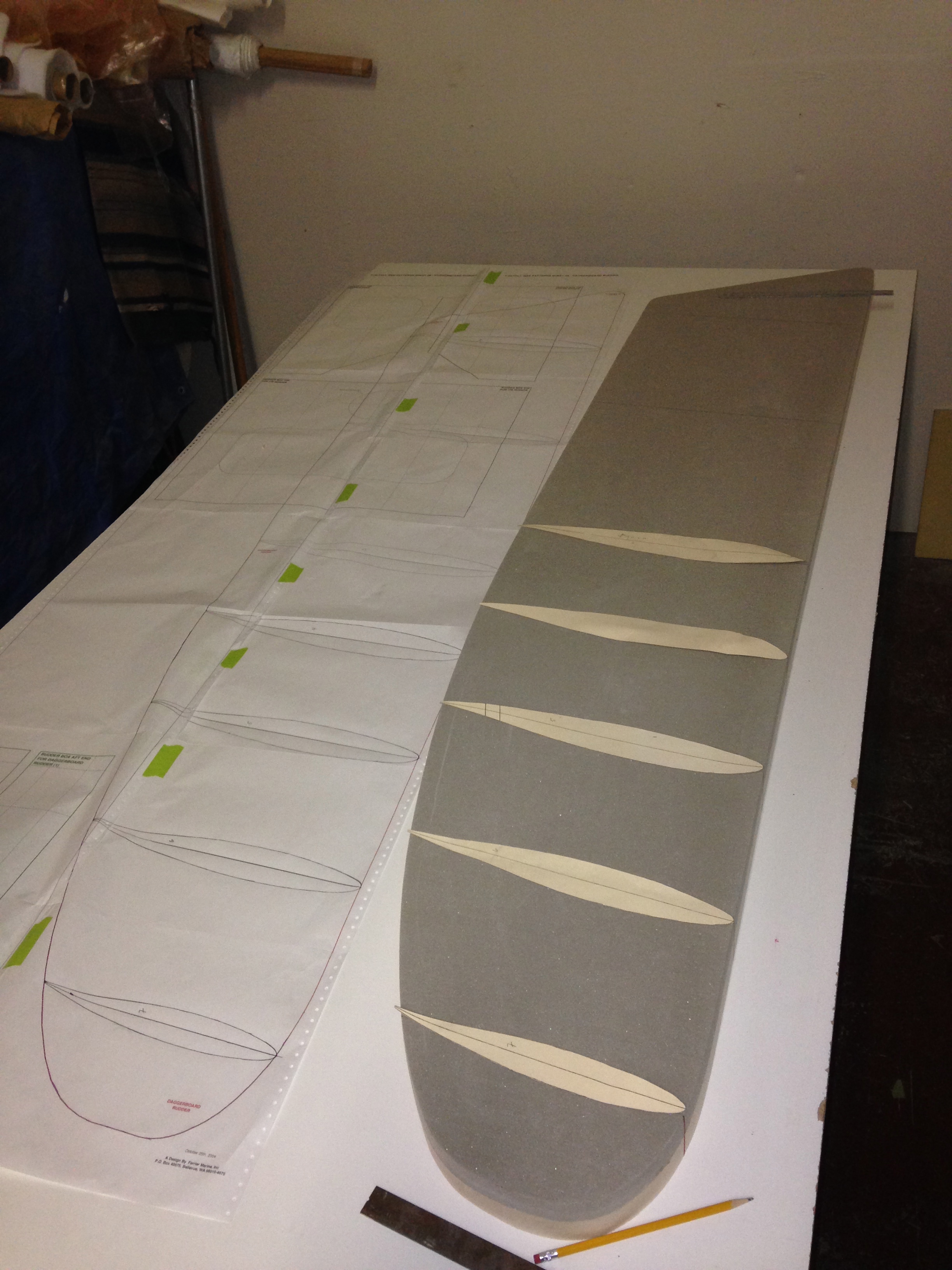
Seems there are lots of ways to unlock the shape of your rudder hidden in a big block of foam. After receiving many tips from the Farrier boat forum, we followed Andrew’s advice on his Trivita F22 build blog. Create contour lines from the shapes indicated by the plans at seven spots along the length, and use the router to ‘terrace’ the rudder.

20140308-200302.jpg

20140308-200336.jpg
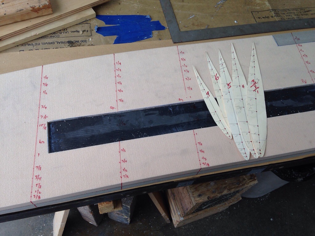
On the first side I used a narrow bit and cut depth grooves on the lines, intending to hit the troughs with spray paint to use later as sanding guides. That turned out to be overkill, and on the other side a wider bit worked just fine, taking all of the material for that depth, before adjusting the router depth for the next contour line level.

20140308-200916.jpg

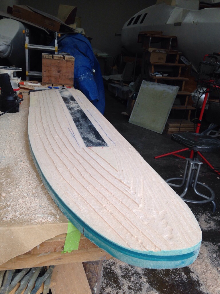
Here’s a huge thanks to Andrew / Trivita for his detailed writing about adding an epoxy-fill to serve as a solid holding ground for the centerline all along the rudder’s edges. See the dark green stripe here:

20140308-201222.jpg
This was cut with a quarter-inch wide x half inch deep roller bearing bit, simply set to the 1 1/8″ centerline before any shaping, but after the high density inserts were added. This hard edge is massively helpful in shaping, and if Farrier was still selling plans, I’d bug him to make this a standard practice.

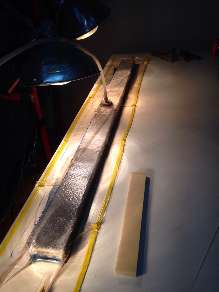
After the first side was shaped, it went in to the bag for the first carbon layer. The idea is to have that solid surface pushing back and holding the rudder level when shaping side two. And since the bottom side was still untouched, it made the vacuum process easy.

20140308-201743.jpg

This came out looking fantastic, EXCEPT a nasty little mistake of not supporting the underside (empty) area behind the HD insert that will sit at the back of the rudder where it meets the cassette. So of course the vacuum pressure deflected the trailing edge in this spot. See the curve in the section that had to be cut out. And the yellow replacement piece bonded in place.

20140308-202127.jpg
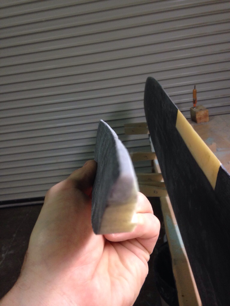
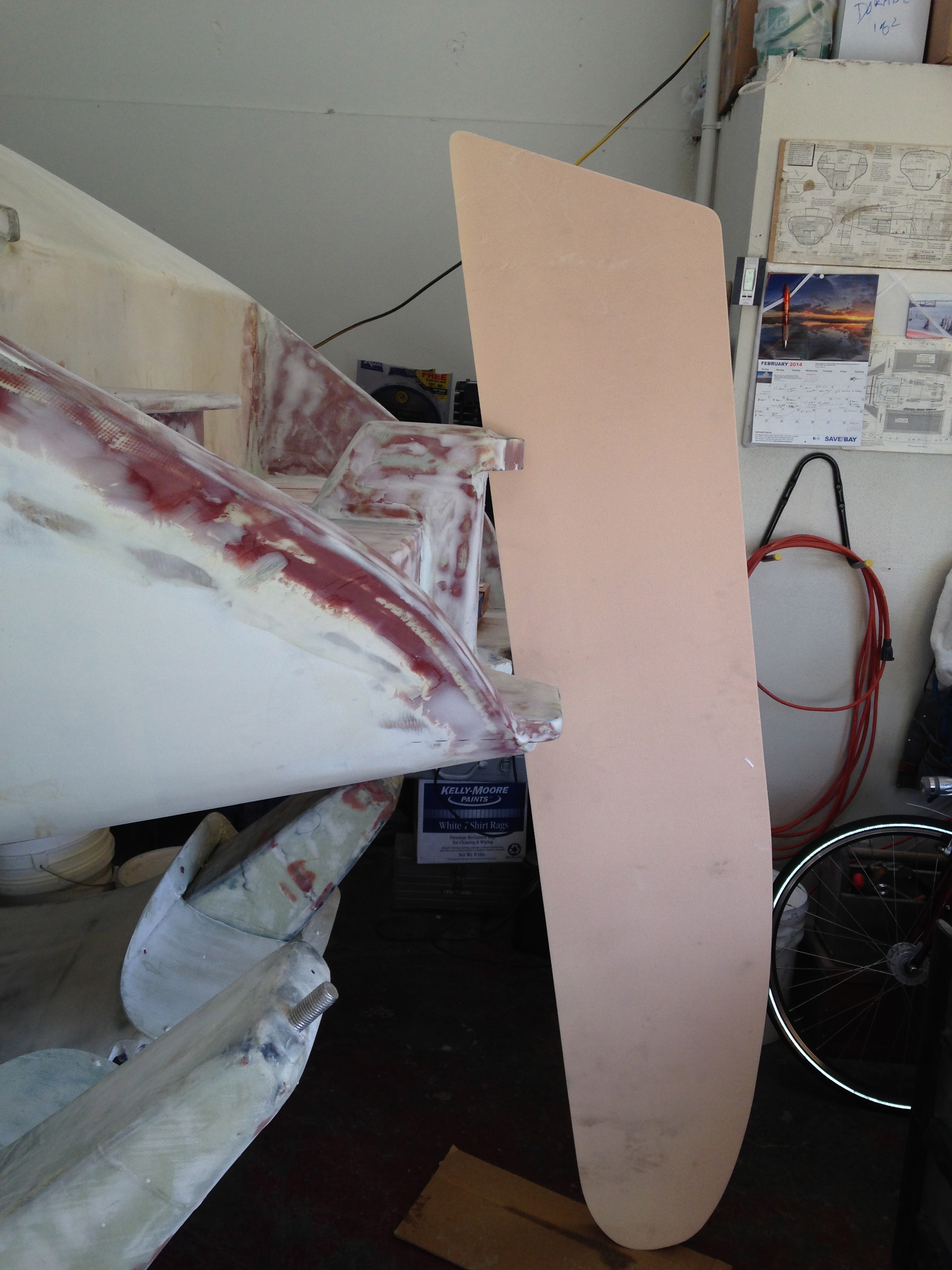
That will get its “side 1” carbon patch next and we can get back to finish shaping side two. All of those router cuts are done, and the rudder sits on the table nicely in its 7 contour shapes up against the carbon side. Here’s the trailing edge currently, with one side in carbon skin and the other still raw foam.

20140308-202433.jpg
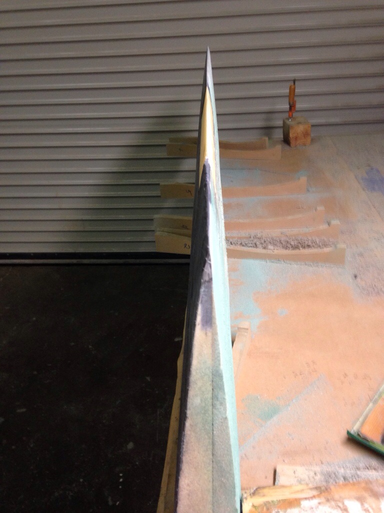
See what I mean about that first centerline back-fill of epoxy putty? Makes a great straight edge!
Tomorrow we’ll finish shaping and get that second skin done. The 14 layers of carbon stiffeners will come next time.

-posted from the road home, a 450 mile round trip today for Griffin’s Tigers win in 14 innings at Eureka. Long way for a good game :)

That’s no ordinary 2×4!

At the core of the F39 rudder lies a five foot long 2×4″-sized piece of triple layer carbon laminated high density foam. Started with 3 strips of 5/8″ core material, with one strip planed down a bit as needed to get the total stack to 1 3/4″, including the carbon. All of this math gets a bit tricky as we allow for the fabric weights, especially the foam ‘rebate’ area where the 14 layers of carbon uni-directional will be placed over this high density insert. Lots of scribbles on the note pad, and the final figures penciled on to the plan book for posterity (which means me building the backup rudder in a few months – or maybe Jimbo gets to do it?)

Recall earlier issues with the vacuum pump – well, it was all technique. Started this run with a clean table and simple bag – the pump drew down to 25″ of pressure within seconds, and this piece came out great.

20140303-002332.jpg

Next the rudder got cut for this insert, plus the two small ones – disregard the prior post comment about putting them in later. I asked for help in the FBoat forum; lots of intriguing ideas and the most-sense-to-me approach is Andrew’s F22 Trivita centerboard forming story. I especially like his centerline groove all the way around the outside of the foil blank. You’ll see that in a few days, once I figure out the router jig needed.

Along with the big carbon bi-directional wrapped spine, there are two more HD inserts at the tiller stock area on top and the cassette breakaway area on the trailing edge. Rather than fill the whole 2 1/4″ gap, we noted from the profile the max final width in these areas and used only that much HD. These pieces got centered using temporary shims underneath during the glueing tonight.

20140303-003107.jpg

20140303-003125.jpg
Remember that the peach and grey ‘halves’ of the foam core are different sizes, so that’s why the yellow HD inserts aren’t centered in those colors, but the are centered to the total rudder width.

Tomorrow we’ll take depth measurements from the foil shape templates and mark depth cutting lines along one side of the board. But first we’ll practice the router technique on some scrap. Fingers crossed!

“And a star to steer her by…”

Well, first we need steering, and that starts with a rudder. The thickest section of the rudder is 2 1/4″, so we bought full sheets of 1″ and 1 1/4″ foam core. This is more than enough for two rudders, so we’ll cut out materials for a second rudder along the way of building the primary. This occurred to me while attending the Singlehanded Sailing Society lecture on emergency steering requirements for the TransPac race to Hawaii; gotta have a backup steering plan for offshore races, and most boats depart with emergency rudders that put the boat in to ‘limp home’ mode, meaning they are smaller and usually weaker than the main rudder. But we can make a second rudder that can do the dual duty of replacing the damaged first rudder in the original cassette, or being partially inserted into a backup cassette. Need to think more about that backup – with only a few F39s sailing, I’m not aware of anyone having worked this out yet.

Work started with big thanks to shop-neighbor Michael Metela Woodworking for the 16 3/4″ rips on his perfect-straight huge table saw. Then we glued and vacuumed the panels together for two 2 1/4″ rudder cores.

IMG_0728 One piece was set aside for working after the boat is launched, and the primary was cut out roughly with a jigsaw and shur-formed to the right shape. This thing is BIG – about six and a half feet tall. In this photo, note that it will ride about a foot and half lower than the floor height allows here. It will also be angled so the bottom tip leans forward of the pivot pins, helping to balance out the helm feel.

IMG_0757Tonight will drift off to sleep thinking about how best to start the shaping of the rudder core. That began with making the profile shape templates, copied from the plans. The manilla pieces will be traced on to wood (MDF probably) and made in to female shaping guides. Gross amounts of the foam will be removed with the Makita power planer (hand held), then the fine work with the shur-foam and sander. Figuring here it’s best to shape the whole thing, then go back and cut out the sections that need to be replaced with the high density foam inserts. You’ll see that developing in the next post.

IMG_0760There are a number of steps before wrapping the rudder in its finish fabric, but it was quite luxurious to open up the carbon fiber double-bias fabric today. Spun black gold was the first impression (which coincides with the credit card bill).  Pretty stuff, but as an ocean going boat, this beautiful material will get covered up under high quality paint. Oh well.

IMG_0722

Quick updates…

… Mostly because I got Mom pretty worried about the vacuum pump! The guys at Fiberglass Supply in WA diagnosed over the phone, and it sounds like it’s all about not drawing the full vacuum, so the pump was overworked and passed oil as vapor. Lesson is to stop the pump rather than limp along with a partial bagging, and we’re pretty sure the pump is fine. We’ll use it hopefully tomorrow eve to affix the handles to the hatch sliders; an easy job that’ll test the system.

Chris Harvey’s going to do a shop day soon so we can build the chainplates – he’s curious about that for his F25Carbon project. In trade, I get a ride on that hot rod – way better than a day in the epoxy barn!

Work plotting out the windshield led to an old floor lamp standing in for the fancy mast, and some cardboard for the boom. Oops, the gooseneck on our beautiful Canadian mast is WAY too high! Spoke with Cole at U-spar who will now lower it to get the boom top 32″ above the deck. This means a whole new Tides Marine track because they are single-piece extrusions. Ouch. But ours will get sold to another U-Spar mast, so it’s not too bad. I took our cues from Yellowfish and the F39 plans. 8 batten pockets and 10 slides. And after hearing the price of battens, Holy Crap we need to try and make those. Let’s see how much carbon is left after the rudder and dagger.

Christmas came again today, as the foam core and bi-directional carbon showed up on a semi truck. Very excited to get the rudder started. Because it’s so tall and skinny, I needed the full 4×8′ sheets of foam core (about $400 for 1″ and 1.25″ to make the 2.25″ base). There’s room for two rudders on there, so I bought most of the extra carbon fiber needed to make a second one. This is one ‘spare’ that makes a LOT of sense at sea. Dad, we should pick a day very soon when you can come up and start tracing out the rudder from those big plan sheets (I know you like the old carbon paper!)

Lots of good comments are coming in re: windshield and dodger. While we sort thru all that, i simply turned around and went back to work on the aft cabin sliding hatch; could have installed a $500 glass deck hatch, but the simplicity of a slider and hatch boards system will also give much easier access based on our cockpit shape. So I’m being careful to match the style between the aft and main hatch areas. More photos will come once it’s not all full of boring looking clamps.

Photo of the day is the award for the Summer Splash “dinghy race”. Kind of an inside joke, but we touch the mug each day as a talisman for getting the boat launched this summer and making it to Catalina by September. Keep working, Carter!

20140204-235331.jpg