Dining and navigating

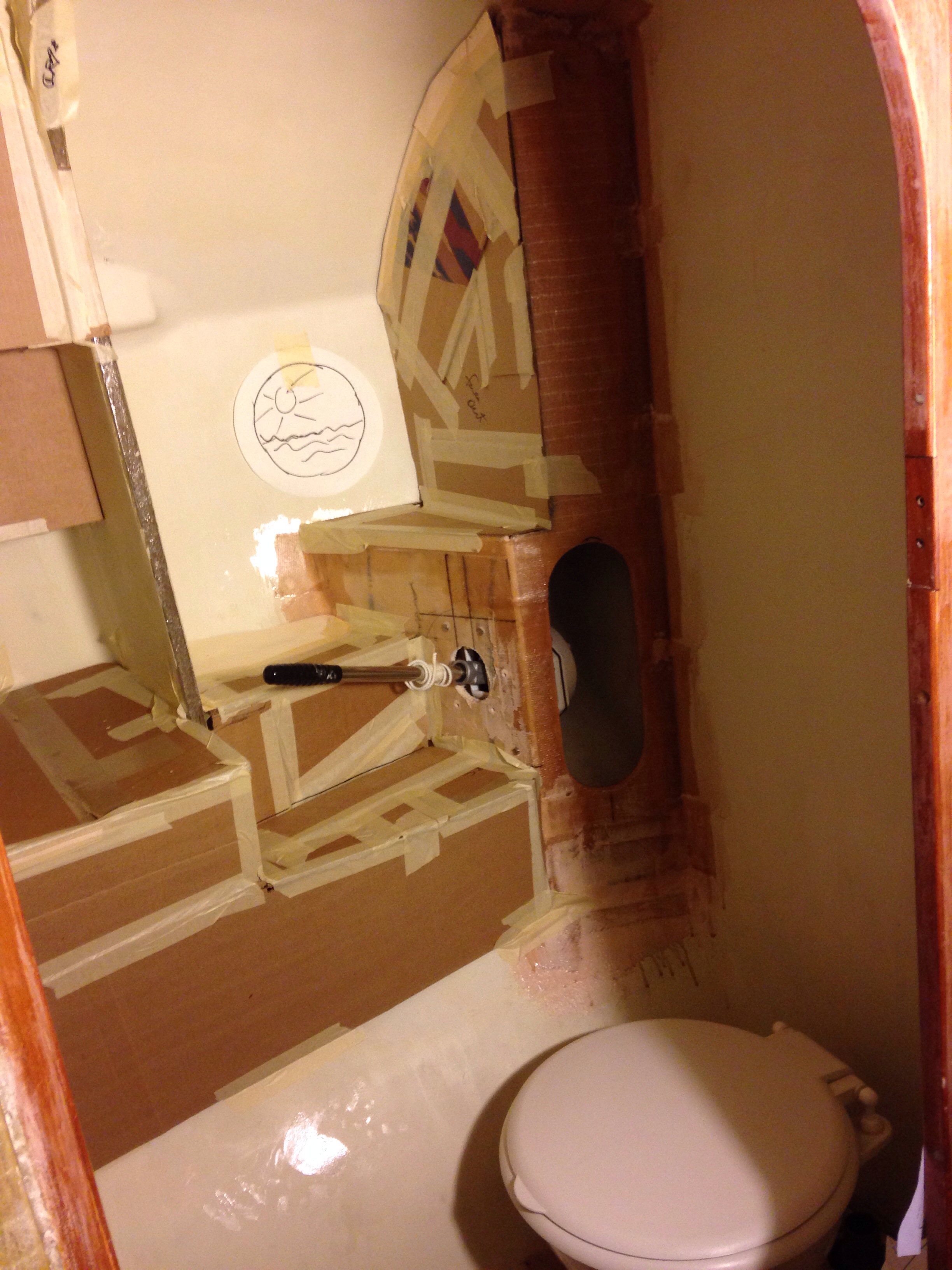
Well the boat shop has been busy but there hasn’t been time to post here. The work has moved back to the interior while some final steering and anchoring parts were ordered. I met with a marine electrics specialist to discuss wiring the boat, and agreed to have Joe create a systems schematic as our blueprint. While he prepares the specs and develops the parts list, we’re back at the boat planning the cable runs, panel location and tricks to conceal all the wires while also keeping everything trouble-shooting accessible. Captain Holway will be very happy when he sees how the electrical access turns out.

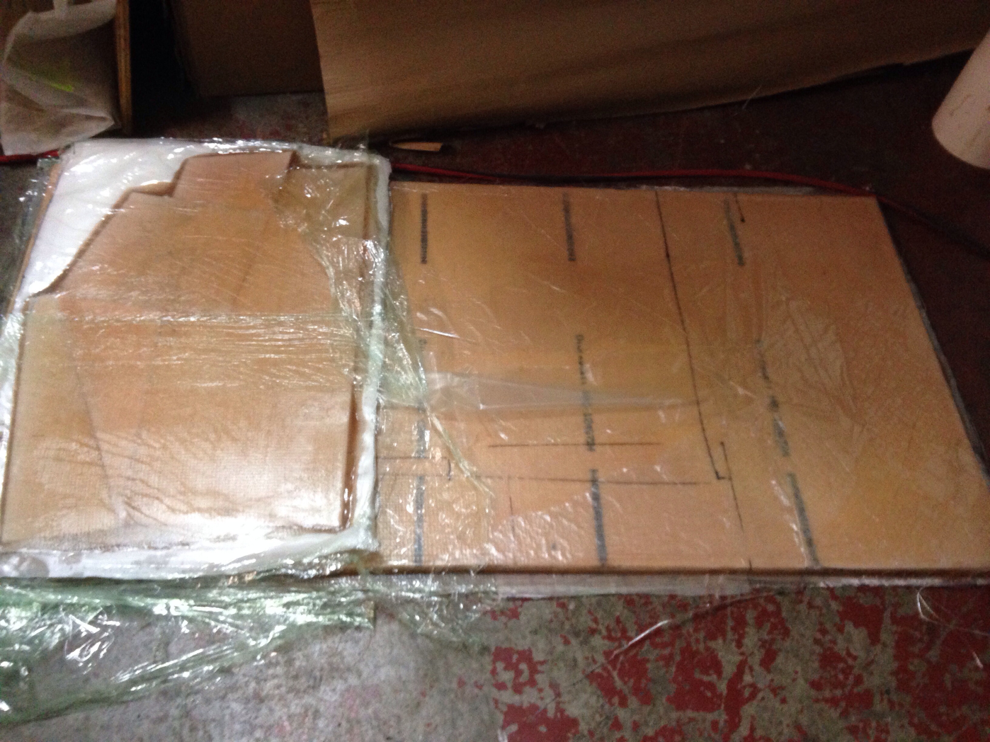
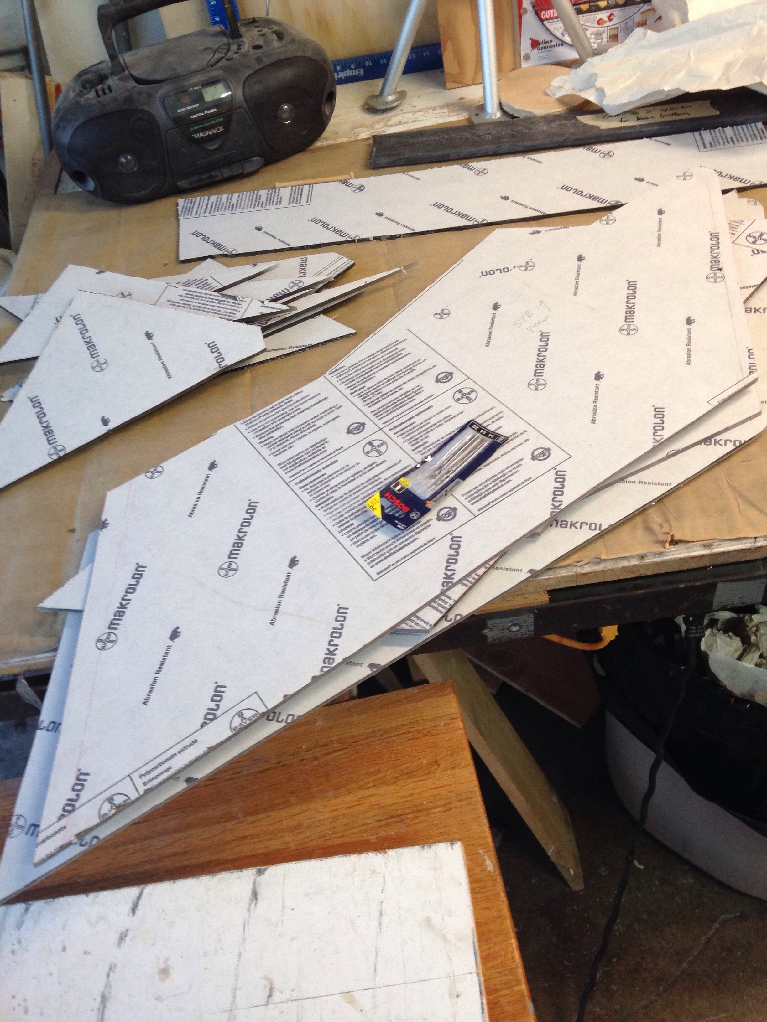
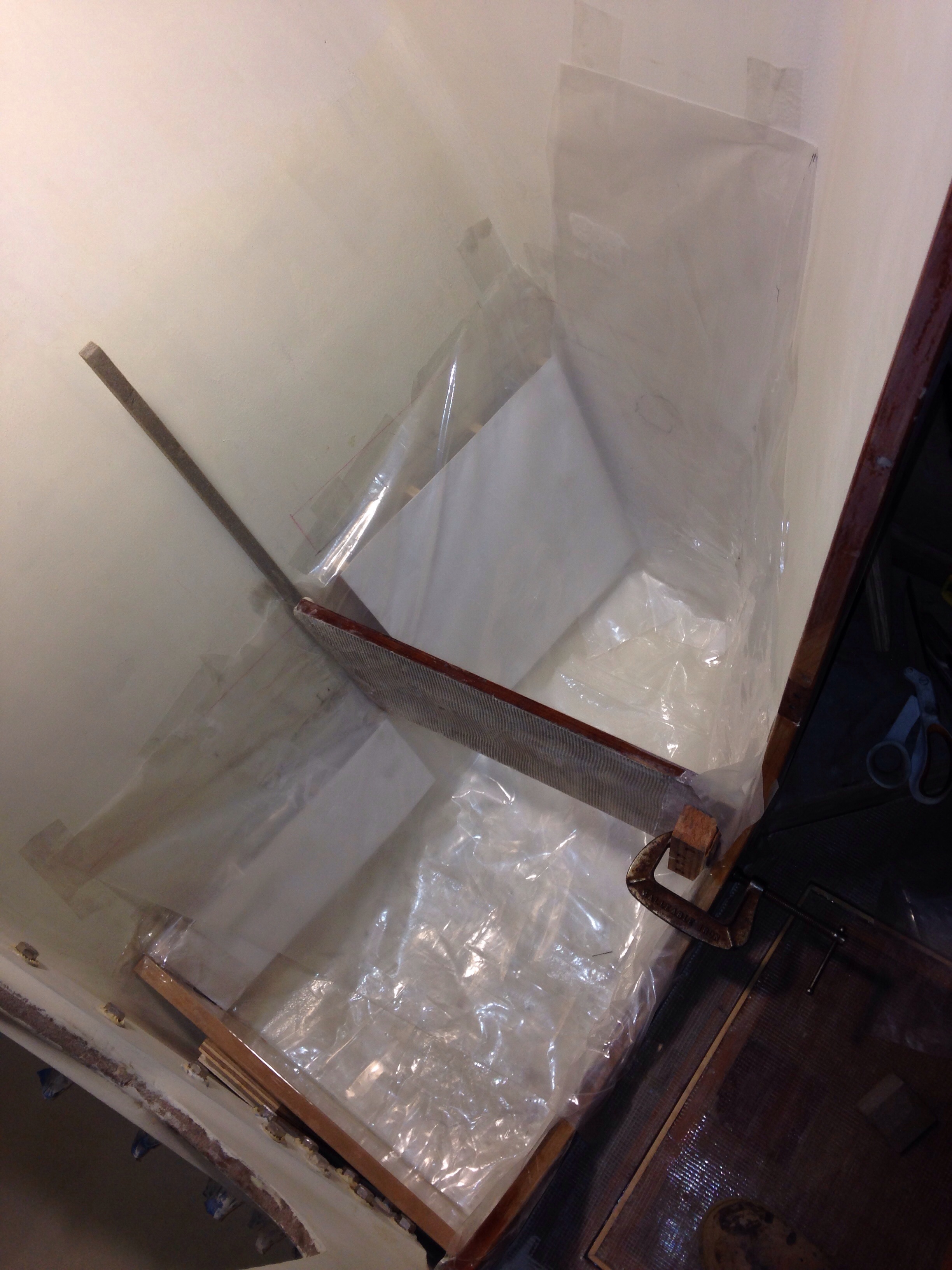
After the head, we moved on to the dressing/wardrobe cabinets and now the nav station and galley. All done first in cardboard as templates for the foam core fiberglass panels.

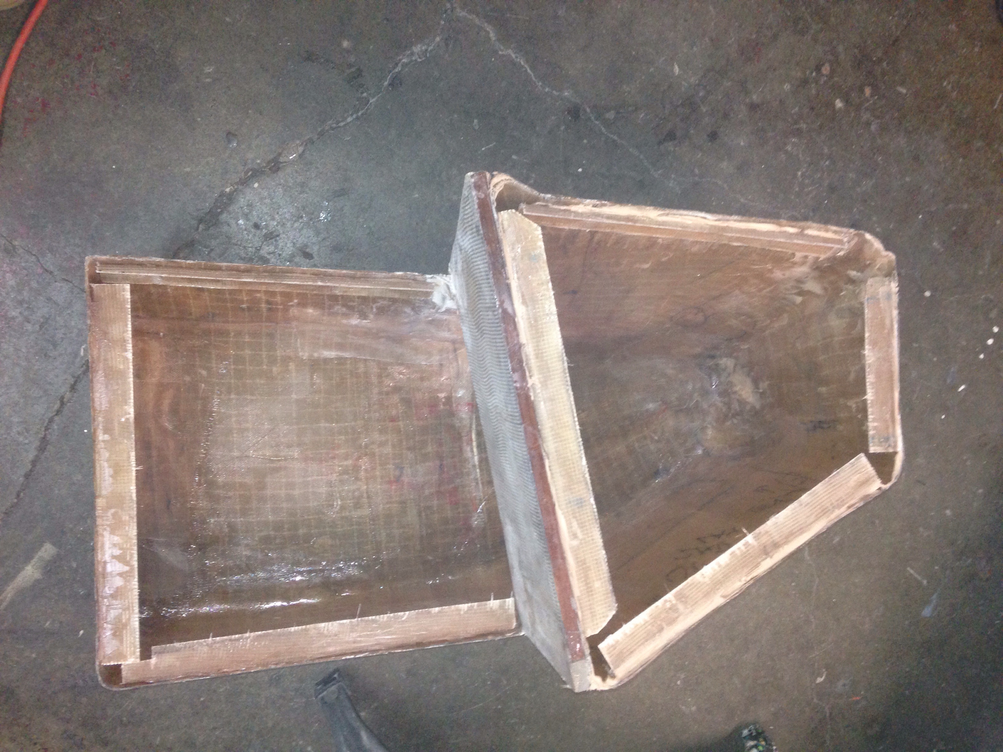
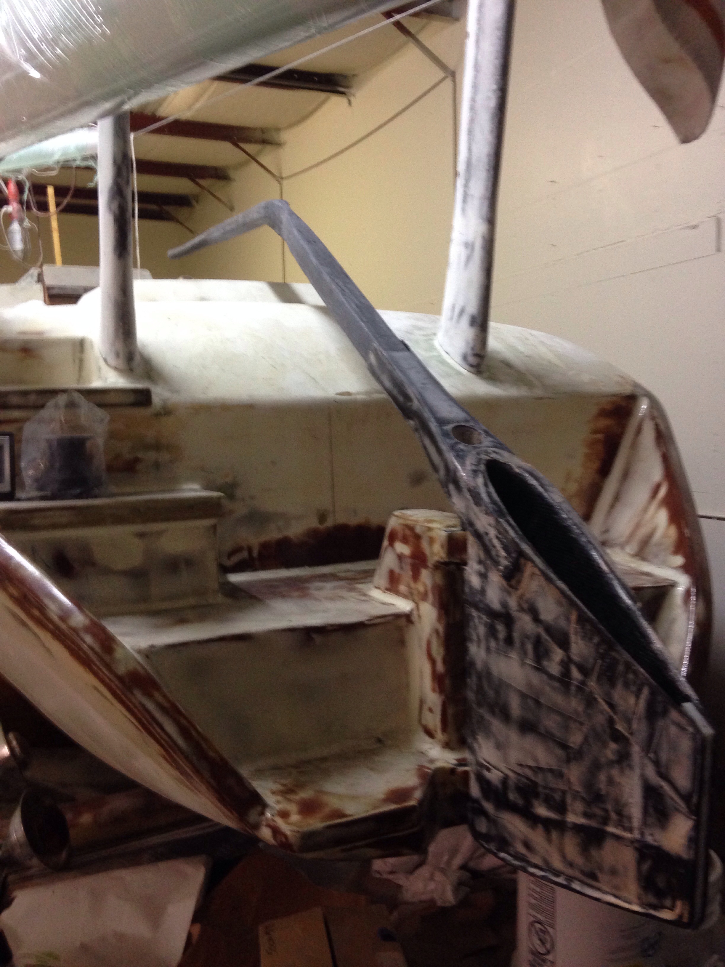
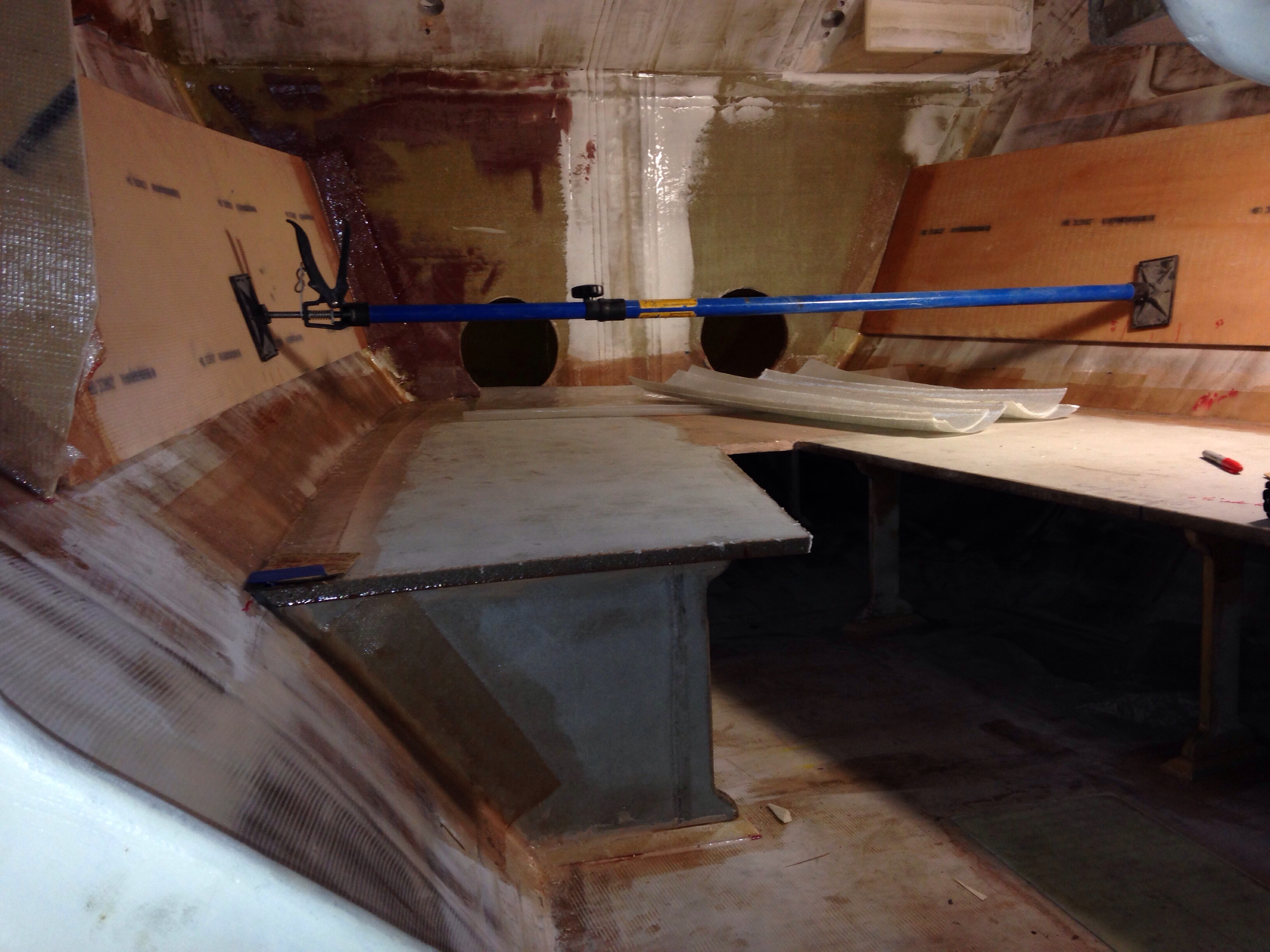
Here’s some seat back storage in the dinette, looking aft towards the galley.

20150210-002412.jpg
Then panning left; the light tan bar in the middle serves as the backsplash to the galley counter and stove.

20150210-002534.jpg
The galley shelves all got bonded to the hull walls tonight.
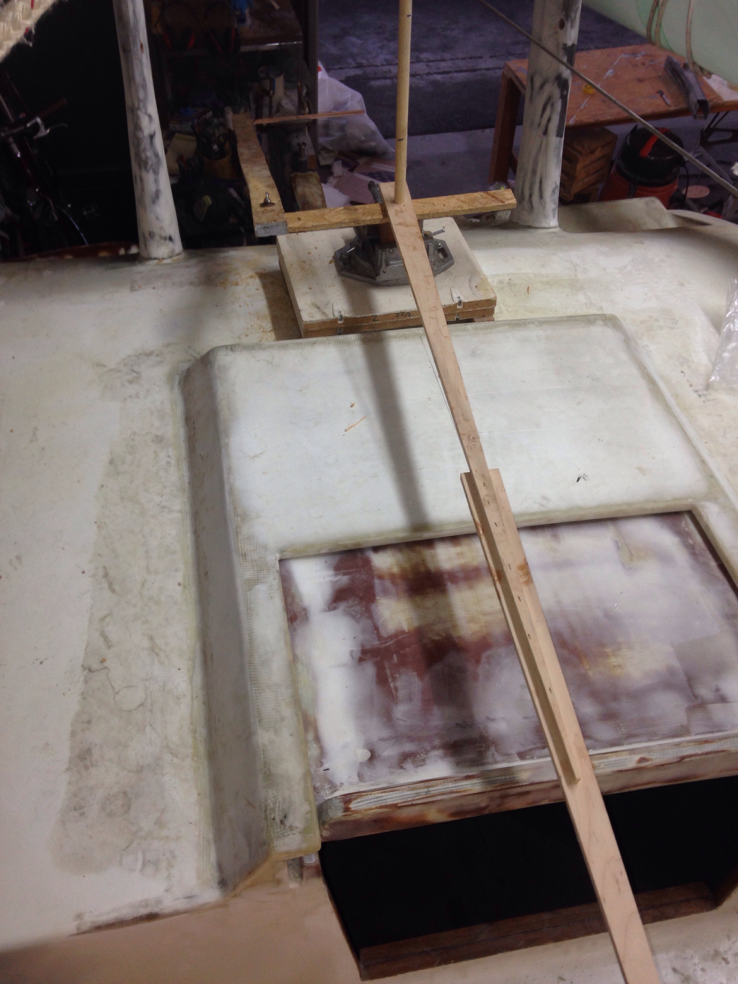
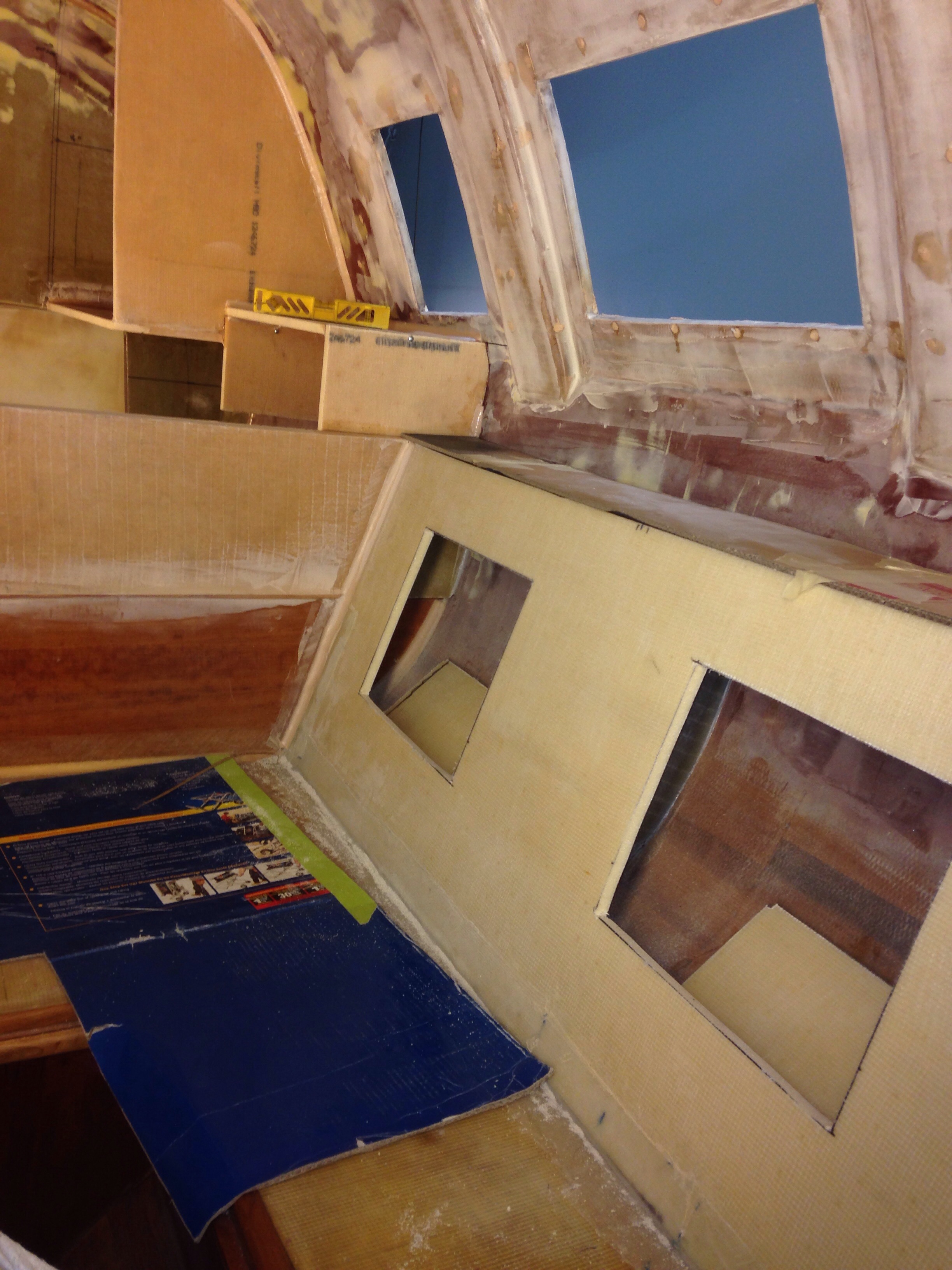
The big hole where you see the orange cord disappearing is the space for the stove/oven unit.

20150210-002651.jpg
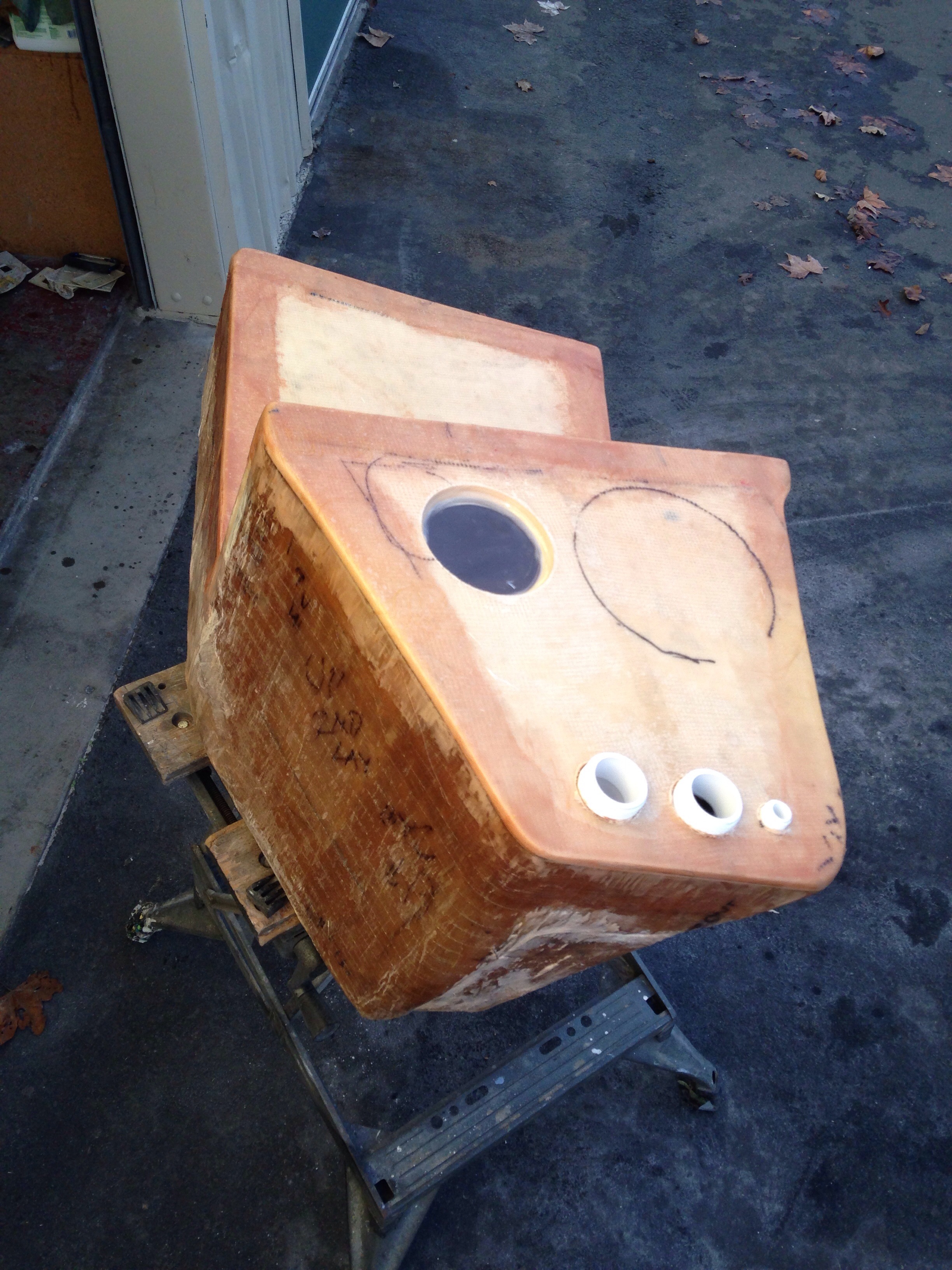
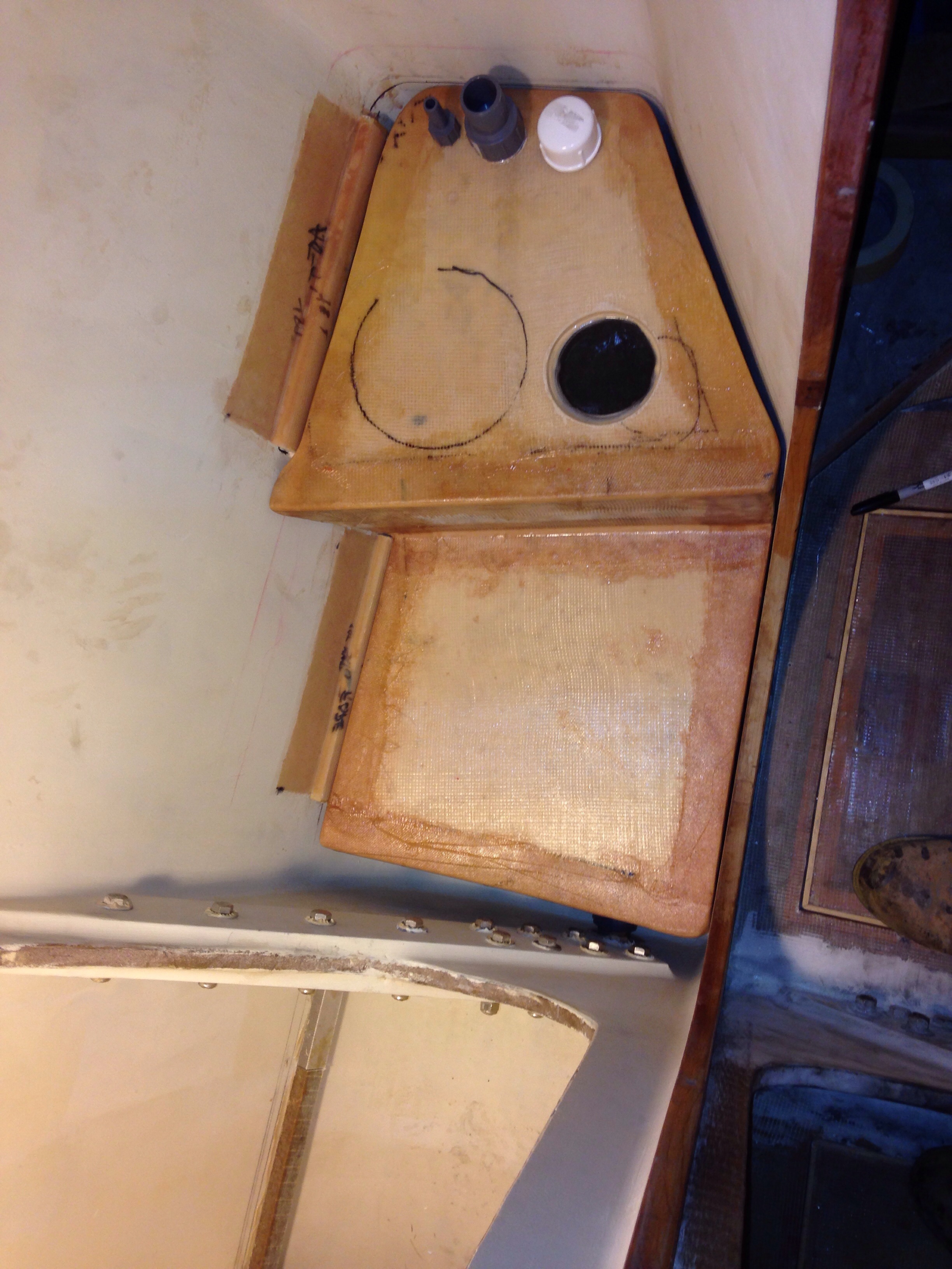
The freezer box is now faired in with its extra cubic foot extension, and now awaits paint before final install of the cold plate and refrigerant/compressor tubes. This thing is a tight fit – the black pen lines on the sides are where the side walls of the freezer box meet this back panel. We had this box dimension when shopping at the boat show, but this got pretty snug!

20150210-003255.jpg
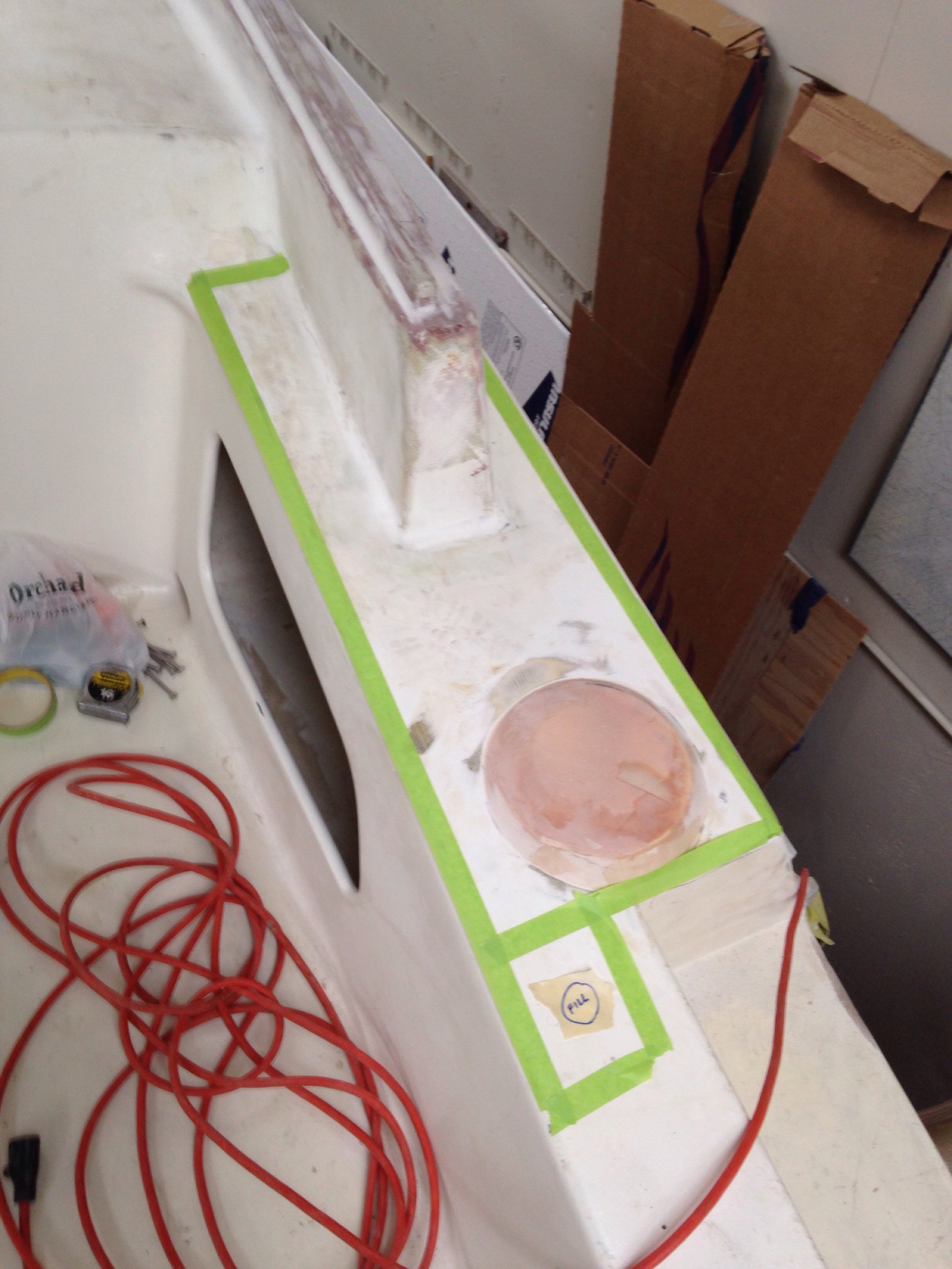
Worked wrapped at 11pm tonight with a push to get the radio / electronics cabinet installed above the navigation desk. The large cut-out is to make this face panel hinged for easy access to wiring and installation of various nav and communications components. There’s a foul weather gear locker to the right, a handheld electronics cubby above that, and a sloping cabinet below the desk for charts. The desk’s wood trim was roughed in with fir, but needs some skilled woodworking to make this be a proper focal point in the boat’s fit & finish. Any fancy wood inlay ideas for the desktop out there?

20150210-003919.jpg

Big like a bear paw

The first shipment of standing rigging parts came in from Colligo Marine. These are the lower anchors for the cap shrouds – 2 of the 3 big lines that hold the mast up.

20150130-080321.jpg
We needed to have these parts in hand to properly size the “chainplates” to build in to the outer float hulls, receiving these anchors. These things used to be big steel plates bolted through the hull with huge chains attached to them. Instead, we’ll make them in carbon fiber, light and strong.
Grapefruit in photo gives some scale; these parts are at least 3x the size of similar parts on the F27. Colligo’s work here is beautiful.

The head compartment cabinets are all faired in, ready for paint. Need to make a couple of doors, and the L shaped part in the right of the photo is a removable section for easy access to the toilet plumbing.

20150130-081010.jpg

Now we’re repeating the process of cardboard mockups for the dressing / clothing cabinets outside the head area, and the galley cabs. Jeanne came down to the boat and we mapped it all out yesterday.

Down on the workbench all of the new steering components got completed and faired out for paint. Just need to get a couple of bushings in then we can mount it all up and show you.

20150130-081301.jpg
And that’s the edge of the windshield in that photo, also FINALLY ready for paint. So much fussy detail sanding and fairing on that intricate big part, and it was frustrating me so badly that I set it aside for months until Charlie came along with a fresh attitude and tamed the tiger. Thanks man!

Adventures in cardboard & carbon

Since we’re saving time making the bow sprit from aluminum stock, that eliminated the anticipated fun of trying to make a carbon fiber tube. But we found an outlet – the six foot steering connection rod you’ll see soon between the new tiller pivot point and the rudder cassette.

I don’t have much success getting all-around-glassed parts off the mold or mandrel, So thought we tried the method where you start with a thin fiberglass layer and make a lengthwise slit to get the new tube off the mandrel.

20150119-173200.jpg

20150119-173221.jpg

20150119-173239.jpg
Once this thin tube was free, we rewaxed the mandrel (which was a piece of metal electrical conduit) and slid the tube back on with the idea that the finished carbon layers would not get stuck to the mandrel. Since we’re “free styling” on this project and it’s the primary steering linkage (a REALLY important part) it seemed that five wraps around with 9oz unidirectional carbon was prudent. Well that many layers of hot epoxy plus the vacuum bag smashing it in and no PVA mold release, etc meant no way was that finished piece sliding off the mandrel. So we made another slit and went back and resealed it afterwards. The result is a pretty thick tube that is comforting-ly stiff when you lean hard on it with no flexing.

20150119-173818.jpg

20150119-173839.jpg
The only metal in the steering system will be stainless steel nuts and ball joints embedded in each end of this tube, plus the bolts to connect pieces. Everything is built now but the rudder bearing I bought isn’t right and needs to be replaced. So stay tuned for the completion soon on that project.

And now to cardboard… It’s not the most elegant way to dream up bathroom cabinets but it works for us. The trick here was designing around the hand pump for the Lavac head and the big mounting brackets where the port side forward beam bolts to the center hull.

20150119-174403.jpg

20150119-174446.jpg
If you’re wondering, it takes six quarters of NFL championship games to cut, recut and generally fiddle with angles to get that mockup done. (poor Packers!) You’re seeing 14 panels that need to be made, adding up to roughly 4′ x 6′ of surface area. Large sheets of double sided laminations were curing on the vac bag table during the two football games.

20150119-175040.jpg
And today began the cutting and fitting, like solving a big jigsaw puzzle. One nice trick for cabinet face openings is lining up center points of 4.5″ hole-saw cuts and connecting the arcs.

20150119-175357.jpg

20150119-175416.jpg
It’ll probably take a few days to get this all built out, as there are many intermediate curing steps on adjoining all the panels.

Sticker shock

A month ago I showed you the sketch and placement of the gas tank, based on the bid request sent off to ATL bladder tank co. The quote came in today; $2560! That’s nuts. The whole engine was less than that. No wonder that company serves government agencies. Oh well. We’ll look in to making a fiberglass tank, custom fit like the toilet tank.

We did spend $450 on a 4’x8′ sheet of smoked-grey Lexan with special scratch resistant coating. This included a minor panic in the Sacramento parking lot when the two 4×4 cut down sheets wouldn’t fit in the car (because someone wanted to drive the sport car, not the truck – duh). I tried to remember the final window height and had them further cut another 14″ on each panel. Fit in the car now, and turned out to be JUST tall enough once back at the shop. Lots of cuts were done:

20150108-204533.jpg
If anyone else is doing this, here’s the right jig saw blade.

20150108-204621.jpg
Lining up the windows for drilling was a two person job, taking almost a full day to get it all done right.

20150108-204740.jpg
These shots show the silhouette of the actual window in the cabin, vs the larger ‘glass’ panels on the outside. We’ve maximized the viewing area from the cabin, honoring structural considerations, trying to get a bit of that open saloon catamaran feel (yeah, Arlene, I don’t want Jeanne to see your beautiful cat’s interior until our boat is done :)

A couple of these windows, plus two on the back cabin, are slated to get opening ports inset over the Lexan. Kind of a floating window within the window. It makes sense when you see it on the nice Benetaus at the boat show.
The new steering setup is coming along; making various parts in carbon and will be able to show it complete soon. We’re also scrapping the complex carbon bowsprit build and ordering a smaller, lighter piece of aluminum – thanks to some sage advice. All good. The only trouble right now is getting in to the 45 degree shop each morning. Hard to get rolling much before 10 right now!

20150108-205607.jpg

20150108-205623.jpg

$#!? rolls down hill

The bathroom is never big enough, right? Because our hull bottom is so skinny, the head compartment is cramped and every inch of space needs to be used efficiently. So what goes under the toilet – well, the holding tank makes sense. Thank you Mike L for insisting on that one :). One wants the “black water” tank as large as possible for lazy cruising days, so as to minimize trips to the dreaded pump out station. Rather than buy a expensive, too small tank, we made one that fills the space available. First the blank canvass …

20141222-174852.jpg
Now line it with plastic, but NOT like this. Using the loose bag produced nasty ripples along the bottom. Had to cut those out and redo with form-fitting plastic tape instead applied to the hull shape.

20141222-175043.jpg
The L shape means the tank is both under your feet and under the toilet base.

20141222-175139.jpg
That whole unit lifted out after some prying, and the top pieces were made on the vacuum table. Along with some heavier laminations for the floor and shelf that will sit just above the tank.

20141222-175309.jpg

20141222-175325.jpg
Rather ugly for my first ever tank build, but it held water under testing.
The outlet to the sea is at the bottom, while the inlet / dock pump out, the breather vent, and a spare clean out port sit on top. Rather than installing an expensive and wire-consuming monitor system, there’s a visual level gauge on top – a window we won’t inspect too closely!

20141222-175704.jpg
After sealing it all up, the tank slides in place. The hull-facing wall is inset 3/4″ to allow for a bonded-on high density bolting flange (on the wall, not the tank) that will take the weight of the toilet and user, as opposed to actually pushing down on the tank.

20141222-180010.jpg

20141222-180026.jpg

The black pen circle is where the toilet will sit on the shelf just above this tank, but the toilet is not connected to the tank. An exit hose runs from the back of the toilet, up through a pump and a loop up above the waterline, then down in to the tank. The good news is this design means no waste stays in the pipes, which is usually the cause of nasty smells. We’ll see the head installed and the shower floor come together in the next post, and maybe some cardboard mockups of vanity counter / cabinets.

Back on deck, we hung the near finished boom in place and set up the Delta Vee main sheet. Well… The long-tiller steering isn’t going to clear so it makes sense to build a linkage steering system. Messed about with the geometry today until getting the right pivots and control arm lengths.

20141222-180436.jpg

20141222-180502.jpg
The steering action is fast and the tiller throw much shorter; this is a much better solution than the first, including a nice way to attach an electronic tiller pilot independent / redundant from the wind vane system. Farrier’s plans call for all this gear to be inside the aft cabin, but I saw that on a completed F39 and it really interferes with the cabin living space. Other owners would not like the steering gear exposed on deck, but I like the simplicity and obvious inspection ability of the gear in plain sight. Thinking of using a flanged rudder bearing to anchor the tiller pivot, and some combination of carbon bars and stainless steel rods & ball joints for the linkage. Type 304 SS ball joints are easily found – thinking we’ll use those and carry extras vs. hunting for rare type 316 SS ones. Any comments back about that?

Steering complete

The 9′ long steering tiller fit in to the rudder cassette head to complete this project. There is still cosmetic work to do, but it’s nice to know we could pilot the boat now if all this rain keeps flooding the county.

20141210-232905.jpg

20141210-232923.jpg
The tiller makes a full sweeping path across the whole cockpit to get the desired 50 degrees of swing from extreme port to extreme starboard. I think we’ll assume this is comfortable and take it out sailing. But if we find either we want less tiller movement in the cockpit or that the rudder is too limited by the tiller hitting the tower legs, then we will retrofit a linkage system, something like this one on F25c Mojo:

20141210-233438.jpg

There are two more primary carbon fiber parts to build, the float-hulls chainplates and the 8′ long bowsprit pole. We’ll start on the plates once the shroud end Terminators get here from Colligo. And this box arrived today for the pole – 20′ of 50″ wide carbon uni to be done in a wrapping fashion and add up to the target wall thickness shown in the F39 plans.

20141210-233937.jpg
We’re pretty excited about that little bit of blue plastic; it’s 10′ of shrink wrap sized to fit over the laminated pole and get heated for a nice even squeeze to hold all that carbon in shape. This $240 shipment, plus a pint or so of epoxy, should yield a pole as good as the +$1k cost pre-built blank tubes. Hopefully this shrink wrap idea works as well as the company’s snazzy how-to website.

30 seconds with Anton

To review, months ago we decided to launch with a gas outboard motor instead of an inboard diesel. But there’s been gnawing angst about having the permanent gas tank inside the main hull and all the associated piping. So yesterday during Anton’s first visit to the shop he dives right in to my current “roadblock” issues. On the gas tank, it takes a half minute of looking around to ask, “why aren’t you putting it in that big cockpit coaming box?” Brilliant solve!

20141206-003202.jpg
We grabbed some quick measurements before hitting the fish taco place; turns out there are about 27 gallons in the cubic inches available. A custom tank could go where the green tape is marked.

20141206-003459.jpg
After an hour of shabby mechanical drawing, we sent off the bid request to ATL flexible fuel tanks in NJ. They make tanks for racing vehicles, insides of airplane wings, spaceships and other tricky applications. The tank will wedge itself in and be very secure. And the fuel line will travel right next to the wiring conduit tube shown a few months back. Here’s what about 6300 cubic inches measures out like:

20141206-003844.jpg
And for the future crew reading this, yes this means the “old” tank space under the galley floor just got reclaimed for beer and wine storage. Jimbo’s wine in a bag will be just right.

Anton and Charlie also solved the steering pivot shaft that would not drop in to place. First was inserting the $60 fancy German bushings.

20141206-004233.jpg
Rather than trying to machine away a tiny bit of the stainless steel shaft, we made a sanding bore out of wood, tape and sandpaper, spun by the battery drill. With a half hour of messing about the shaft seated in all 8 bushings and the rudder swings perfectly (not a trace of slop / wobble)

20141206-004524.jpg
Here’s the cassette holding rudder #1. Note the forward tilt mentioned in a prior post. And that the rudder hits the shop floor about a foot before it gets down in sailing position.

20141206-004726.jpg
And the trim tab rudder #2 can’t have the tab swing unless the rudder is all the way down — that’s an interesting way to “turn off” the windvane effect in the future, ie just lift the rudder up a few inches.

20141206-004929.jpg
And now to finish the steering, the turning arm was built.

20141206-005034.jpg
The forward end gets the foam dug out to make way for the tiller to slide in.

20141206-005147.jpg
A big wedge was then cut from the rear portion so the steering arm could surround the cassette.

20141206-005317.jpg
So now all that stuff is ready for the tiller. The foam core got shaped with proper attention paid to the driver’s end – we experimented with shapes until finding the right size for Mrs. Carter’s hand. Happy wife, happy boat, right?

20141206-005554.jpg
With Keith’s comments in mind, the hoop-strength carbon lamination is curing tonight and the lengthwise unidirectional carbon will be applied Saturday. By Sunday we’ll finally be steering the boat!

Cassette, side 2

We’re now four days in to the rudder cassette build – lots of steps and the result looks very strong.

Here’s the beginning of the steering pivot axis (green tube)

20141124-231811.jpg
That green pipe will be vertical; the increasing angle of the cassette away from the vertical hinge means that the rudder will be tilted forward about five degrees. This is important as the boat rises up on plane and less rudder is in the water, the forward rake helps keep the helm balanced and not get very heavy in the driver’s hands.

There are carbon layers between the tube and cassette, with the rest of the gap filled with foam and putty. (In pink)

20141124-232241.jpg
Next was wrapping the pivot tube in to the cassette structure with four more layers of thick carbon double bias fabric – look for vertical lines towards the smaller end. And about ten layers of carbon uni-directional in the two areas that match up to the hull’s gudgeons – see the thicker sections along the tube end.

20141124-232838.jpg
Ok, this thing is ready for cut-ins at the gudgeon points and trial fitting tomorrow. Then the final step is building the steering tiller. The tiller stub is a built-separate piece that will get permanently bonded to the cassette. Here it starts with a foam core, about 26″ long:

20141124-233412.jpg
This piece was laminated and vacuum bagged with its many carbon layers today and will be fitted to the cassette on the boat tomorrow.

Need to decide whether the 9′ long tiller should be made from wood or foam core and carbon. If carbon, we’ll need to solicit ideas on the fabric layup schedule. Any thoughts?

Better than an 8-Track

I remember fondly the day we tore out the 8track in the Chevette and got a Cassette deck. Dorky car with a Radio Shack tape player – geez. Now we’re getting a carbon fiber rudder cassette on a good boat – I like this a lot better than the high school parking lot.

The cassette is built around the rudder for an exact fit, but it has to be oversized to allow low profile carpet to glue along the inside faces. That gives the rudder a snug fit and abrasion prevention. So to create that 4 millimeter gap it was another trip to the fabric store for some 1mil vinyl. (Wrapped in four layers)

20141119-181426.jpg

20141119-181527.jpg
The photo above shows a wax bead laid along the edges to form a nice radius of the cassette lip.

Made a paper pattern to get the vinyl sized just right:

20141119-181813.jpg

20141119-181836.jpg

The white plastic at the bottom will be the sacrificial break away area in case the rudder strikes something – the cassette is designed with a give-way point rather than destroy the rudder or the stern hull structure.

Then six layers of carbon fabric made an 1/8″ cassette body.

20141119-182204.jpg
After the epoxy cured a few hammer blows got it separated from the rudder, and looking good.

20141119-182420.jpg

20141119-182507.jpg
And this is roughly where this piece will mount on the boat, after many more steps to create the hinge for turning the rudder and the attachment point for the tiller. Probably another 20 hours for this primary steering build.

20141119-182943.jpg

When rudder parts are curing, work goes on in the aft cabin. Floor, bunks, and closet bulkheads are installed. To get the seat backs to conform roughly to the curved hull shape, this telescoping “Third Hand” tool is pushing the two sides in to shape while the fiberglass dries along the bottom edge and I can go eat dinner :)

20141119-183349.jpg

With all the cassette talk, the radio got tuned to 80’s music in the shop all day. Took a break from NPR for AC/DC and Duran Duran sing alongs – hope that’s not the chemicals getting to me!