Yes, but it’s a DRY heat, dear

Well, the oven run from the last update got to about 115. So we upped the heat bulb count to 4 x 250 watt plus 5 x 125 for 1600+ watts to heat an 85 cubic foot box. Also added some R13 attic insulation around the box and a small circulation fan inside. With the afternoon sun beating down on the works, we hit and held 160 today, so beam #1 is officially post-cured. Just need three more warm sunny schedule free afternoons.

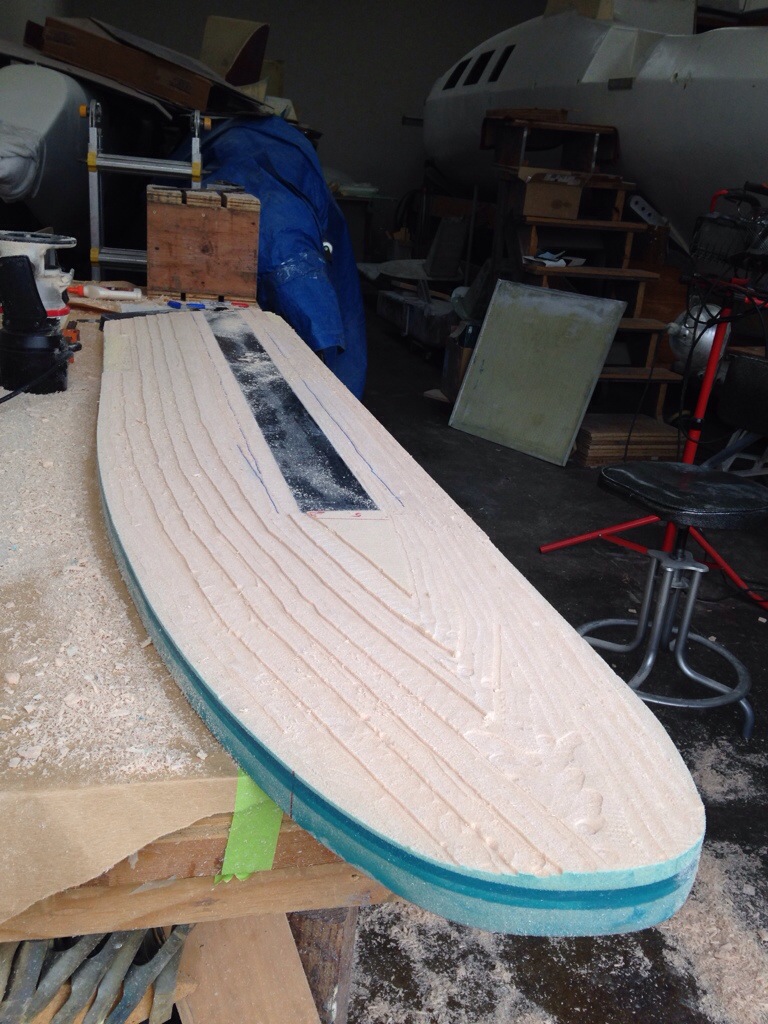
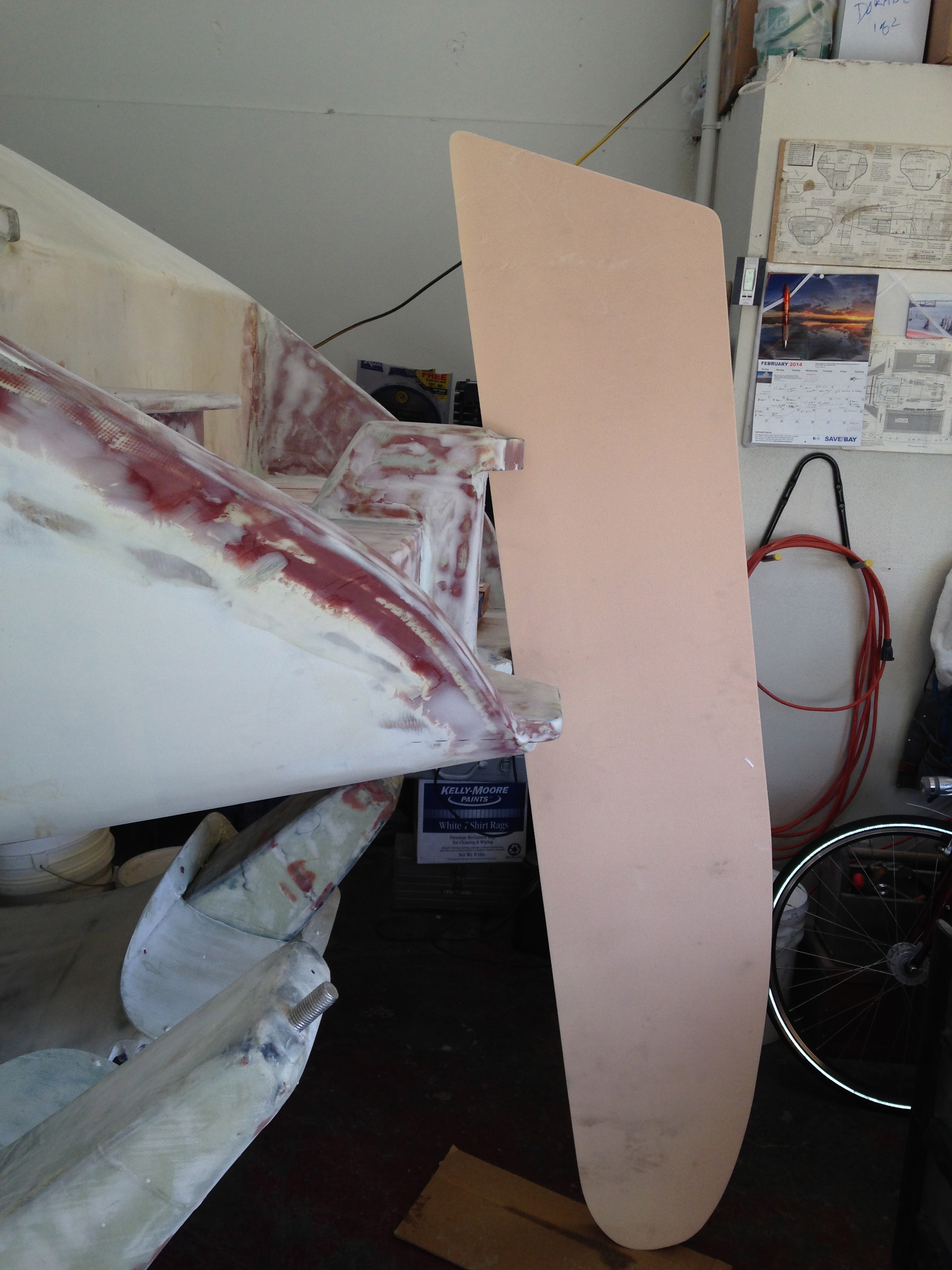
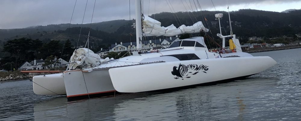
Started fairing the rudder and it looks way better quickly. Photos will come once the fairing is done and we’re in primer. Really need to get this done so the steering components can begin. For those following Fram’s build, with all Henny’s amazing engineering steps, you will see the polar opposite develop here. Simple, crude and hopefully just as effective as the great feeling of steering the F27.

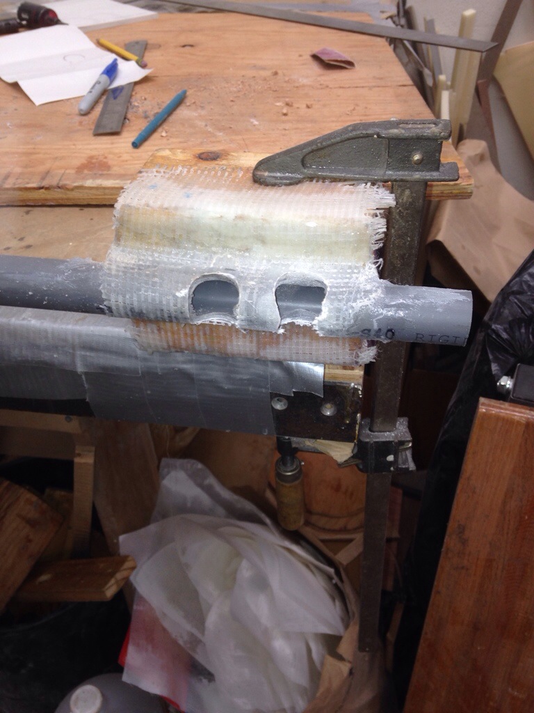
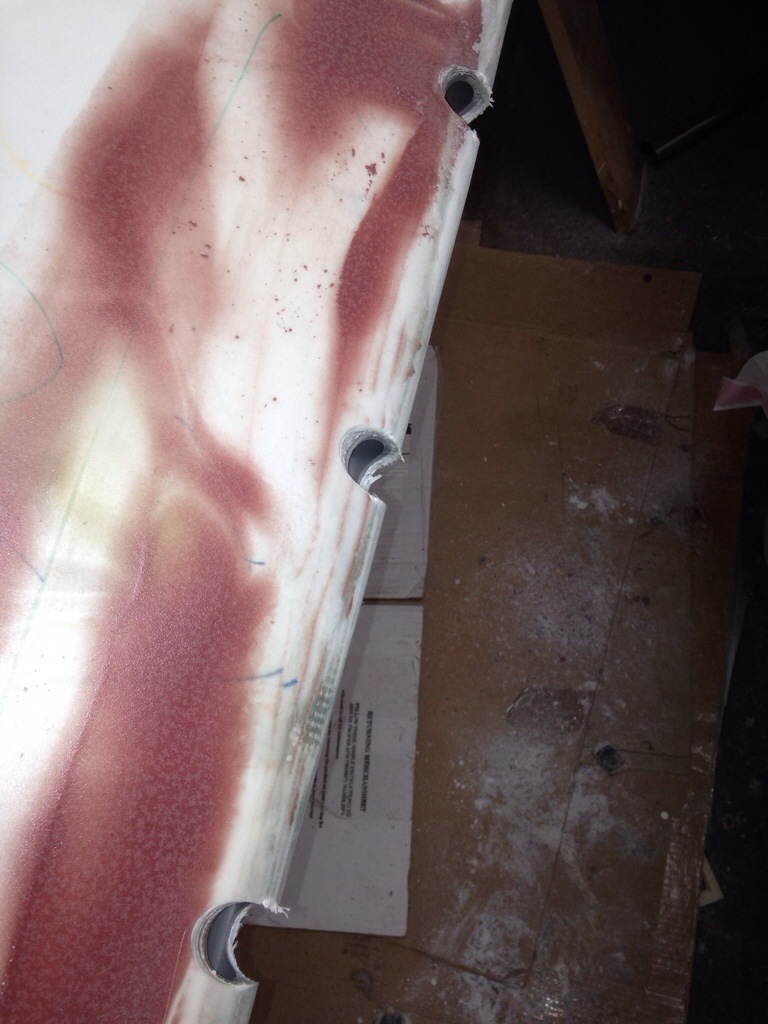
Back to the windshield, the rope pass-thrus came out quite smartly. Here they are being cemented in place yesterday, and were cut off flush this morning.

20140319-003043.jpg
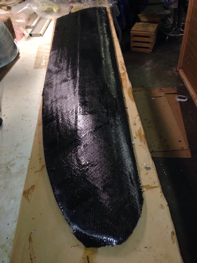
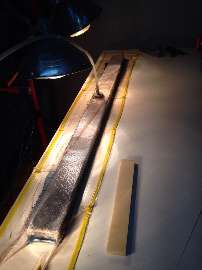
Next the center portion and the port side got 16oz glass and an awkward-shaped vacuum bag.

20140319-003154.jpg
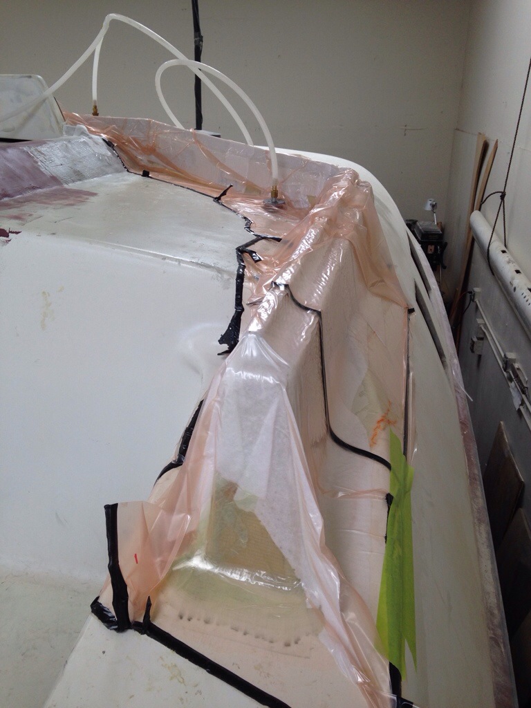
The bagging is getting more proficient, but I still spend too much time chasing leaks probably because of improvising around weird shapes and surfaces once the glass is already wetted out. Two things I wish I had learned in advance: (this note is for new-to-bagging folk)
Attach all the sticky tape in advance to one side of the bag material, doing that work flat on your big table. Things like adding the sticky tape on one end after the glass application totally screwed things up.
Work a trial run with everything dry and plan out where extra baggy material is need to conform to staggered / stair step shapes. Otherwise it’s really frustrating to have a whole bagging set up but one big corner gets stretched to the point where there is no actual downward pressure on an inside curve or corner. This stuff sounds easy but it seems a real experienced art form to me. Tricky to get it right and I keep learning to make the bags bigger, although my inner tight-wad pushes back on materials (perceived) waste. Let’s see if tomorrow night’s port side windshield frame gets done more smoothly than today’s.

For Schildknecht

Yea! The rudder is complete and it’s very exciting to have this vital part of the boat here on the table instead of the plan diagrams not too many days ago. The last touch today was to wrap the leading edge in Kevlar – not in the plans but we decided that about 12 more ounces of weight to put a bullet proof vest-like protection on the front where crap hits a rudder seemed like a smart trade off. It’s the remnant fabric from the full hull length keel-line protective strip that went on the main hull 15 yrs ago.
Can you see the color scheme of the Pittsburg Steelers? (The rest of you can stare blankly while Bill S. laughs)

20140315-225455.jpg
And that foam blank to the left is another rudder to build – for Colin’s rehab Coronado 15 project. Figured we might as well do an airfoil shape too.

Stood the rudder up in position so you can see the difference from the similar shot of the foam cutout a couple weeks back. Makes more sense now!

20140315-225812.jpg

20140315-225848.jpg
In that last shot, see that the rudder will actually drop another 8 inches or so once the floor isn’t in the way.

Writing this tonight while trying not to stare at the curing oven thermometer. Space heaters didn’t work, and like others I’m on to trying heat lamps. Got to 115F with about 600 watts of lamps. Added another 540 watts tonight and we’re passing thru 105 as I type. The Applied Poleramic folks want their ER2 to post cure at 160 for two hours. They told me by phone that I could substitute some time for heat, like maybe 140 for four hours or so. If we don’t get far enough the shop neighbor has a friend at the car painter – we could haul all the beams, the rudder and other structural stuff over there for an evening bake off. Guessing he’d charge a few hundred and it’s a big pain in the rear to transport this stuff. Tonight’s red lamps should look quite familiar to Mom – remember keeping all your dogs warm in the shed on the freezing Sonoma nights?

20140315-230630.jpg

107 and still rising. Time to go cut out glass fabric for the windshield frame.

Baked Beams, anyone?

It got warm in Santa Rosa and my thoughts turned to summer BBQ – hot dogs, baked beans, cobs of corn…
But really we need to post-cure the epoxy in the beams and steering parts, so we need a big oven to reach and hold 160 degrees (F) for 2-3 hours per session. Made this from Sheetrock and ripped 2x4s, just big enough to house one forward beam resting on its furniture dolly.

20140313-234540.jpg
Pulled the top on, and it started working right away, but the fan-aided space heater hit a safety kill setting at about 95 degrees. So tomorrow we’ll follow Gordie Nash’s advice and find a cheap baseboard wall heater at Home Depot. And perhaps have to take some license pulling out any safety settings if it has a brain.

The rudder took shape nicely and has now gone thru the carbon lamination steps. Each side got a staggered 14 layers staring from the top down. There’s some extra wraps over the upper edges, and the outer skin of the second side went in the vac bag this evening.

20140313-235056.jpg
The last step will be adding a bit of Kevlar tomorrow to the leading edge, just to provide some impact resistance.

While the rudder was in a bagging step, we free handed an idea for strengthening the slot where halyards will pass thru the windshield back to the winches. Simply take 24″ of PVC pipe and tape it to some foam:

20140313-235441.jpg
After waxing the mold, we made three trips around with wet fiberglass and let dry overnight. Cut it in half the next day and pop out the molds from each 12″ piece (that’s the step in the photo). I need to take a winch to the shop and mock up all the exact positions for these line guides, then we can cut the windshield frame openings to match and glass these tunnels in.

20140313-235721.jpg

And here you can see the decision on how to affix the removable windshield to its base. Bolts will go in horizontally along this grey wedge that has been set at the proper angles desired for each window pane going around the frame.

20140313-235920.jpg
This windshield base is now ready for glassing this weekend. After a bike ride. :)

Building the rudder

Seems there are lots of ways to unlock the shape of your rudder hidden in a big block of foam. After receiving many tips from the Farrier boat forum, we followed Andrew’s advice on his Trivita F22 build blog. Create contour lines from the shapes indicated by the plans at seven spots along the length, and use the router to ‘terrace’ the rudder.

20140308-200302.jpg

20140308-200336.jpg
On the first side I used a narrow bit and cut depth grooves on the lines, intending to hit the troughs with spray paint to use later as sanding guides. That turned out to be overkill, and on the other side a wider bit worked just fine, taking all of the material for that depth, before adjusting the router depth for the next contour line level.

20140308-200916.jpg

Here’s a huge thanks to Andrew / Trivita for his detailed writing about adding an epoxy-fill to serve as a solid holding ground for the centerline all along the rudder’s edges. See the dark green stripe here:

20140308-201222.jpg
This was cut with a quarter-inch wide x half inch deep roller bearing bit, simply set to the 1 1/8″ centerline before any shaping, but after the high density inserts were added. This hard edge is massively helpful in shaping, and if Farrier was still selling plans, I’d bug him to make this a standard practice.

After the first side was shaped, it went in to the bag for the first carbon layer. The idea is to have that solid surface pushing back and holding the rudder level when shaping side two. And since the bottom side was still untouched, it made the vacuum process easy.

20140308-201743.jpg

This came out looking fantastic, EXCEPT a nasty little mistake of not supporting the underside (empty) area behind the HD insert that will sit at the back of the rudder where it meets the cassette. So of course the vacuum pressure deflected the trailing edge in this spot. See the curve in the section that had to be cut out. And the yellow replacement piece bonded in place.

20140308-202127.jpg
That will get its “side 1” carbon patch next and we can get back to finish shaping side two. All of those router cuts are done, and the rudder sits on the table nicely in its 7 contour shapes up against the carbon side. Here’s the trailing edge currently, with one side in carbon skin and the other still raw foam.

20140308-202433.jpg
See what I mean about that first centerline back-fill of epoxy putty? Makes a great straight edge!
Tomorrow we’ll finish shaping and get that second skin done. The 14 layers of carbon stiffeners will come next time.

-posted from the road home, a 450 mile round trip today for Griffin’s Tigers win in 14 innings at Eureka. Long way for a good game :)

Not quite full time

Being a relatively productive Type A, I departed Epsilon with the game plan of hitting the boat shop full time. It’s been six weeks since the Jan 20 start, so that should be at least 6×40=240 hours, right? But the figures penciled on the calendar each shop session added up to 198 thru Feb. It’s been great to spend time reconnecting at home, cycling with friends, visiting with Allie and score keeping for the Analy Tigers. And it’s much easier to say Yes to good marine tasks like helping Stephen Marcoe ‘salvage’ the Formula 40 cat Tuki from her 2013 dismasting insurance settlement. We were quite a scene at the ramp pulling that big race cat without a real trailer or crane. Tuki is an amazing big boat in need of an adventurous new owner.

Build tasks are taking longer than my estimates. For ex, the hard dodger mockup was a guess of 25 hours, but there’s already 21 in just the windshield base. I figured the beams needed 50 hours for fairing, but it’s been 127 hours of learning to do fairing well, plus lots of details around the wing net lashing points, lifeline stanchion bases and a boarding ladder mount. Jeanne has the best perspective – she said this week it’s important to let the boat take the time it needs to get finished properly and not cause burn out. If there are trips in 2014 where we should charter a finished boat, so be it. That’s a healthy comment from Mrs Carter – but we’re still going to push like crazy to get launched this summer :)
We’ll post hours totals each month as these might be useful for other builders, and it will help with my amnesia in some lovely lagoon some day when another cruiser asks if it was any big deal to build vs buy… And we’ll smile with way more boat than could have been reasonably purchased.
All the pitching-in along the way is so fantastic. Dad took the numbing task of fairing out 75 or so openings in the net lashing tubes – a dusty operation for sure. But my favorite point in the day was realizing that after 3/4 of a century he hadn’t yet played with a big air compressor blow gun.

20140304-232052.jpg

20140304-232346.jpg
(Yes, those are brand new harbor freight car engine hoists about to be dunked in salt water – a whole new definition for disposable tools!)

That’s no ordinary 2×4!

At the core of the F39 rudder lies a five foot long 2×4″-sized piece of triple layer carbon laminated high density foam. Started with 3 strips of 5/8″ core material, with one strip planed down a bit as needed to get the total stack to 1 3/4″, including the carbon. All of this math gets a bit tricky as we allow for the fabric weights, especially the foam ‘rebate’ area where the 14 layers of carbon uni-directional will be placed over this high density insert. Lots of scribbles on the note pad, and the final figures penciled on to the plan book for posterity (which means me building the backup rudder in a few months – or maybe Jimbo gets to do it?)

Recall earlier issues with the vacuum pump – well, it was all technique. Started this run with a clean table and simple bag – the pump drew down to 25″ of pressure within seconds, and this piece came out great.

20140303-002332.jpg

Next the rudder got cut for this insert, plus the two small ones – disregard the prior post comment about putting them in later. I asked for help in the FBoat forum; lots of intriguing ideas and the most-sense-to-me approach is Andrew’s F22 Trivita centerboard forming story. I especially like his centerline groove all the way around the outside of the foil blank. You’ll see that in a few days, once I figure out the router jig needed.

Along with the big carbon bi-directional wrapped spine, there are two more HD inserts at the tiller stock area on top and the cassette breakaway area on the trailing edge. Rather than fill the whole 2 1/4″ gap, we noted from the profile the max final width in these areas and used only that much HD. These pieces got centered using temporary shims underneath during the glueing tonight.

20140303-003107.jpg

20140303-003125.jpg
Remember that the peach and grey ‘halves’ of the foam core are different sizes, so that’s why the yellow HD inserts aren’t centered in those colors, but the are centered to the total rudder width.

Tomorrow we’ll take depth measurements from the foil shape templates and mark depth cutting lines along one side of the board. But first we’ll practice the router technique on some scrap. Fingers crossed!

“And a star to steer her by…”

Well, first we need steering, and that starts with a rudder. The thickest section of the rudder is 2 1/4″, so we bought full sheets of 1″ and 1 1/4″ foam core. This is more than enough for two rudders, so we’ll cut out materials for a second rudder along the way of building the primary. This occurred to me while attending the Singlehanded Sailing Society lecture on emergency steering requirements for the TransPac race to Hawaii; gotta have a backup steering plan for offshore races, and most boats depart with emergency rudders that put the boat in to ‘limp home’ mode, meaning they are smaller and usually weaker than the main rudder. But we can make a second rudder that can do the dual duty of replacing the damaged first rudder in the original cassette, or being partially inserted into a backup cassette. Need to think more about that backup – with only a few F39s sailing, I’m not aware of anyone having worked this out yet.

Work started with big thanks to shop-neighbor Michael Metela Woodworking for the 16 3/4″ rips on his perfect-straight huge table saw. Then we glued and vacuumed the panels together for two 2 1/4″ rudder cores.

IMG_0728 One piece was set aside for working after the boat is launched, and the primary was cut out roughly with a jigsaw and shur-formed to the right shape. This thing is BIG – about six and a half feet tall. In this photo, note that it will ride about a foot and half lower than the floor height allows here. It will also be angled so the bottom tip leans forward of the pivot pins, helping to balance out the helm feel.

IMG_0757Tonight will drift off to sleep thinking about how best to start the shaping of the rudder core. That began with making the profile shape templates, copied from the plans. The manilla pieces will be traced on to wood (MDF probably) and made in to female shaping guides. Gross amounts of the foam will be removed with the Makita power planer (hand held), then the fine work with the shur-foam and sander. Figuring here it’s best to shape the whole thing, then go back and cut out the sections that need to be replaced with the high density foam inserts. You’ll see that developing in the next post.

IMG_0760There are a number of steps before wrapping the rudder in its finish fabric, but it was quite luxurious to open up the carbon fiber double-bias fabric today. Spun black gold was the first impression (which coincides with the credit card bill).  Pretty stuff, but as an ocean going boat, this beautiful material will get covered up under high quality paint. Oh well.

IMG_0722

Does it come with a moonroof?

The UPS truck brought goodies today, thanks to the clearance rack at Defender.com – saved many 100s on this order :)

To further brighten up the main salon, here’s a healthy sized (14″x20″) ceiling hatch. Should make for nice stargazing on cool nights. Vetus brand looks really well made, with the satin finish to match the big Lewmar one over the fore-cabin.

20140219-090000.jpg

The Plastimo Offshore compass is new but since the white dial doesn’t sell well, they reduced it from 225 to 80. SOLD! And will mount nicely in the cockpit.

Also picked up two dorades for continuous ventilation. In the first photo the base is open – look near the black ring at the bottom…

20140219-090335.jpg

That base is spring-loaded, so if water gets in the round tray gets heavy and plunges down to shut off the whole thing. See the difference in this photo:

20140219-090541.jpg

Back to the beams, two have been finished in fairing work and the other two get a big push over the next couple of days. To better handle the uneven face gap from the form frames mentioned a month ago, this time we’ve tried some 2mm “core mat” which worked really well to add some very light weight bulk, and then a thin layer of finish fiberglass.

20140219-091056.jpg
Nice to find the products to help amend minor lapses in finish work!

Do a little jig

Well, not exactly dancing in the workshop, but we did make a drilling jig today and got very nice results with the net lashing points on the beam edges. These slots cut in to the long tubes will allow us to loop small lashing line around a skinny rod inside the big tube, creating anchor points for the nets every seven inches along the beams, the float decks, and along the sides of the main hull.

First up was a practice piece to get the depth right. Cut on the left didn’t take enough of a bite…

20140210-231038.jpg
The drilling jig is simply some hardwood pieces screwed together and carefully drill pressed. It’s enough to get the pilot bit started on the actual work surface, then set the jig aside and finish each cut.

20140210-231624.jpg

These were cut using a one-inch hole saw (the wood-cutting version burned up quickly – needed to upgrade for metal-cut bits). The outer edges point in, following the circle, so another straight cut is needed next.

20140210-231919.jpg

Note the little paper pattern in this photo – that got marked on each hole with about 35 degree legs so the lashing line can run out at angles and not rub.

20140210-232235.jpg
Got both leading edges of the two being-worked beams done. Next is some fine-finish work around these cuts and two of the beams will finally be complete.

And while glue was drying – back to the hatches. Decided to beef up the locking area (it’s also the grab handle) with sturdy aluminum plates. That’s another pound or so added to the boat, but intruder security is the one place we don’t mind taking a small hit on performance wise. It’s a safe house before it’s a race boat.

20140210-232818.jpg

And the framing for the aft cabin hatch is coming along. Style is matching the main companionway area. This work allows procrastination on the hard dodger design decisions. :)

20140210-233104.jpg

Quick updates…

… Mostly because I got Mom pretty worried about the vacuum pump! The guys at Fiberglass Supply in WA diagnosed over the phone, and it sounds like it’s all about not drawing the full vacuum, so the pump was overworked and passed oil as vapor. Lesson is to stop the pump rather than limp along with a partial bagging, and we’re pretty sure the pump is fine. We’ll use it hopefully tomorrow eve to affix the handles to the hatch sliders; an easy job that’ll test the system.

Chris Harvey’s going to do a shop day soon so we can build the chainplates – he’s curious about that for his F25Carbon project. In trade, I get a ride on that hot rod – way better than a day in the epoxy barn!

Work plotting out the windshield led to an old floor lamp standing in for the fancy mast, and some cardboard for the boom. Oops, the gooseneck on our beautiful Canadian mast is WAY too high! Spoke with Cole at U-spar who will now lower it to get the boom top 32″ above the deck. This means a whole new Tides Marine track because they are single-piece extrusions. Ouch. But ours will get sold to another U-Spar mast, so it’s not too bad. I took our cues from Yellowfish and the F39 plans. 8 batten pockets and 10 slides. And after hearing the price of battens, Holy Crap we need to try and make those. Let’s see how much carbon is left after the rudder and dagger.

Christmas came again today, as the foam core and bi-directional carbon showed up on a semi truck. Very excited to get the rudder started. Because it’s so tall and skinny, I needed the full 4×8′ sheets of foam core (about $400 for 1″ and 1.25″ to make the 2.25″ base). There’s room for two rudders on there, so I bought most of the extra carbon fiber needed to make a second one. This is one ‘spare’ that makes a LOT of sense at sea. Dad, we should pick a day very soon when you can come up and start tracing out the rudder from those big plan sheets (I know you like the old carbon paper!)

Lots of good comments are coming in re: windshield and dodger. While we sort thru all that, i simply turned around and went back to work on the aft cabin sliding hatch; could have installed a $500 glass deck hatch, but the simplicity of a slider and hatch boards system will also give much easier access based on our cockpit shape. So I’m being careful to match the style between the aft and main hatch areas. More photos will come once it’s not all full of boring looking clamps.

Photo of the day is the award for the Summer Splash “dinghy race”. Kind of an inside joke, but we touch the mug each day as a talisman for getting the boat launched this summer and making it to Catalina by September. Keep working, Carter!

20140204-235331.jpg