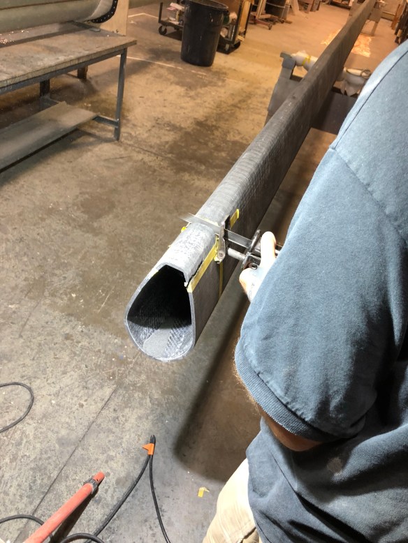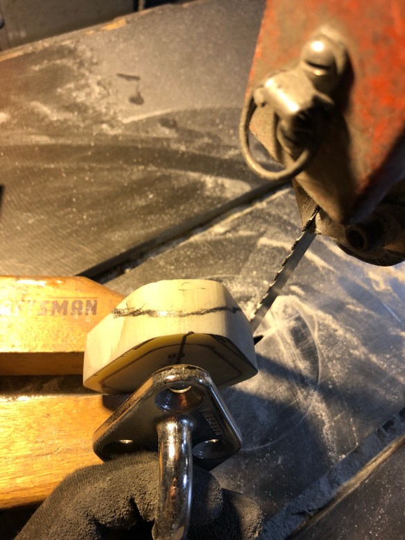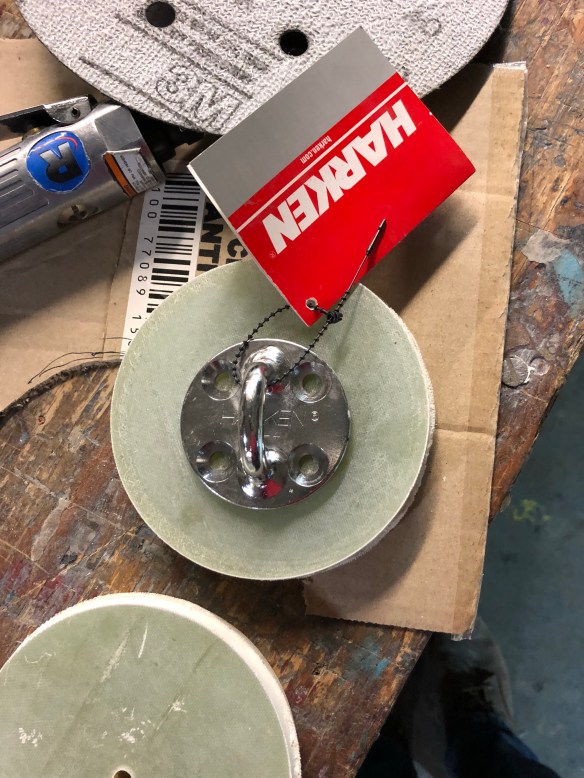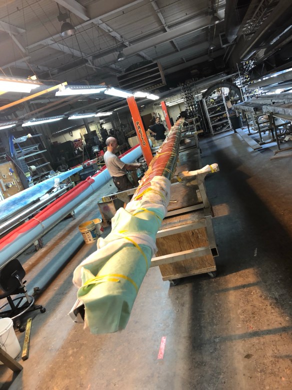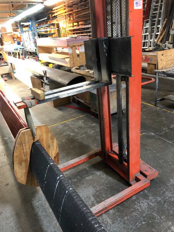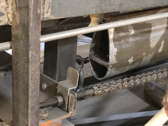
We showed you the completed spreaders about a week ago. Their attachment to the mast had to wait for foreman Will, over on the other big project in the shop (more on that later). Our spreaders are a little tricky to mount, needing both a twenty degree sweep-back and an off-level tilt to accommodate our desired 5 degrees of mast rake (how much the mast leans back from vertical on the boat). All of this gets accomplished with custom wedges on the band saw to cope the spreader roots to the mast wall, and jigs to get the sweep right. 
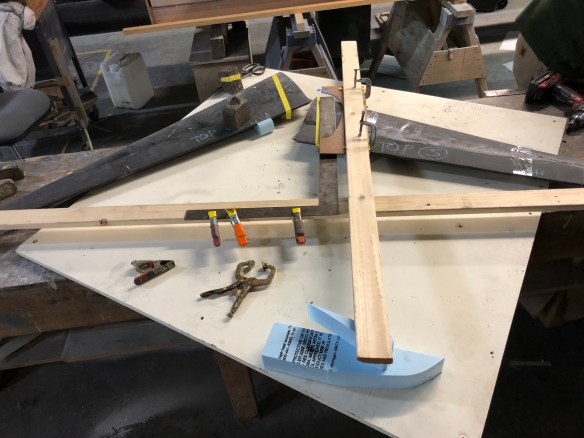

 Because I spent most of three days building them, I could barely watch while Will cut them to fit the mast. But all his calculations and jig prep paid off.


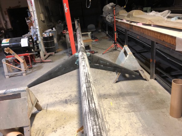 Tonight they are barely tabbed on. Tomorrow we’ll do significant connecting reinforcements. And as both Keith and I have ripped carbon spreaders from a big mast before, yes they will certainly get uni-strapping that connects them around both the front and aft walls.
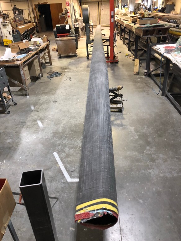
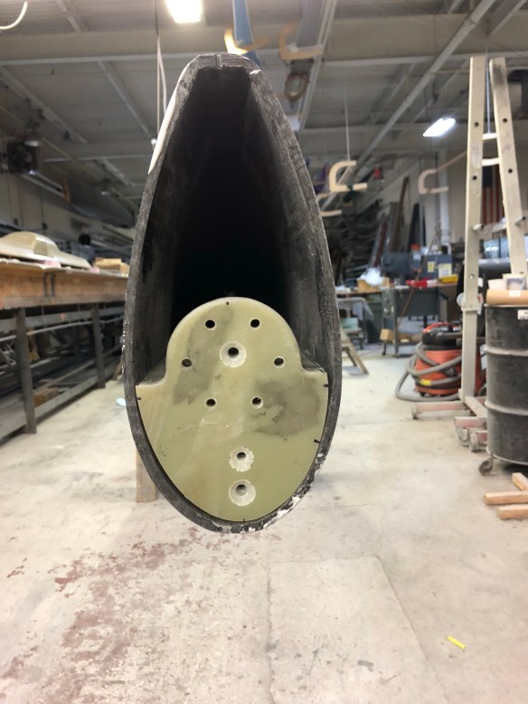
Last week I built the foot insert and was going to wait until it was installed to show you. But we decided to hold off further in case the lower diamond terminals need better access. So here is the unit that will transfer the load from the mast walls into the rotation ball on deck. 


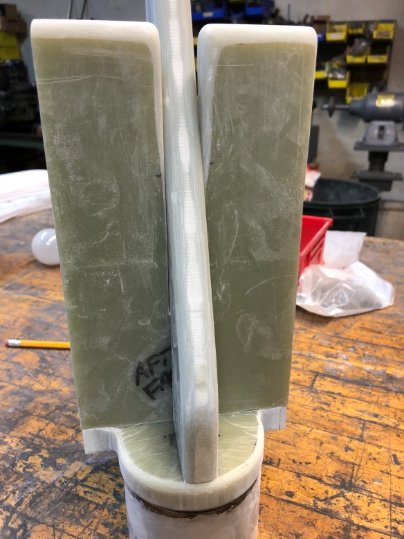
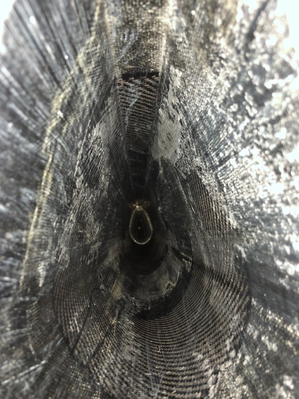
 If you knew our first mast, that six-hole pattern at the bottom is where the same steel cup will be screwed in to the mast. Here’s the view the halyards will see – very clean access around this foot piece, and ZERO protrusions into this mast above the foot all the way to each halyard’s exit. No wires, no cross bars, no bolt heads. Our design goal was a totally clean inside to minimize any halyard chafe on extended ocean passages.
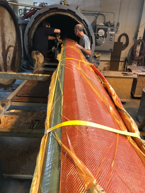
Now a bit of shop politics. Back in June we discussed the bad schedule slipping and the two projects still in front of us. One is a 60′ mast for a charter boat under construction. Luckily for us, the Coast Guard approval has not yet come through on those plans, so we got bumped ahead. The other project is the boom of an older America’s Cup 12 Meter class boat that is currently for sale. That boom is using the same carbon spools as ours, so they were braided back to back. Composite Engineering agreed that if I came to work here they could epoxy-resin-infuse ours first since it would need more finish work. And because ours was infused the night I traveled east, I offered to help infuse the boom so I could see the process they used on our mast. Turns out, the boom’s infusion was much more complicated because its fabric layup changes significantly along that spar, compared to our relatively uniform mast spar. So for you infusion veterans, this means three separate plumbing circuits all had to be managed in one big vacuum bag. One, because once it goes into the autoclave and the whole thing goes to 44psi, having separate vacuum circuits becomes irrelevant. (They shut the vacuum circuits down once the autoclave reaches its own high pressure). In a couple of these photos you’ll see the resin spreading into the peel ply. Notice it go from dry (light green) to fully wet out (dark green). 
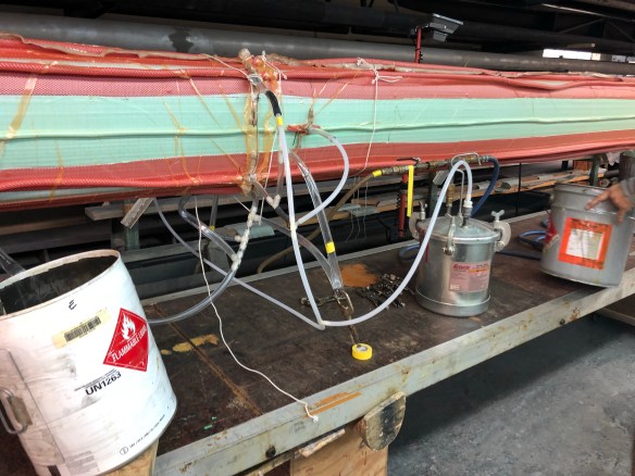
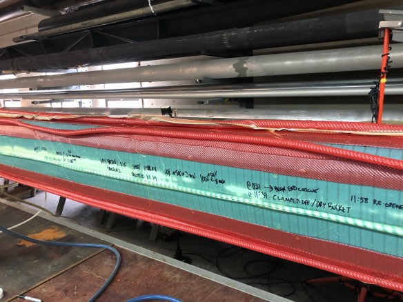

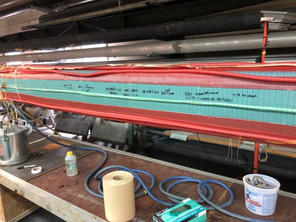
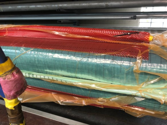
As the rookie, my job of course was epoxy mixing boy. Don’t spill, nitwit!
Once the bosses were sure all fabrics were infused with resin (there was quite a dance to manage on/off timing of three feed and vacuum circuits), it was time for high pressure and heat curing. 


CE ramps their epoxy up slowly( they find this best for eliminating trapped air bubbles), so this was 120F for two hours then a trip up to 275F or so and we left it for the night. It’s all computer programmed, both heat and pressure timing. Because of the multi circuit plumbing, and some VERY heavy carbon layers near the boom vang, we went with extra resin and expected the resin traps to catch the wicked-out excess. The pot closest to the central plumbing picked up it’s full share! That’s wasted money (excess squeezed out resin) but very much calculated into the project management of risk-reduction; you must avoid dry spots in the laminations at any cost.
I said ‘politics’; that includes horse trading. So that the skilled guys could work on our spreaders, I offered to unpack the other customer’s boom. Those disposables (that wick away the excess epoxy) are significant muscle work to remove on these big projects. 
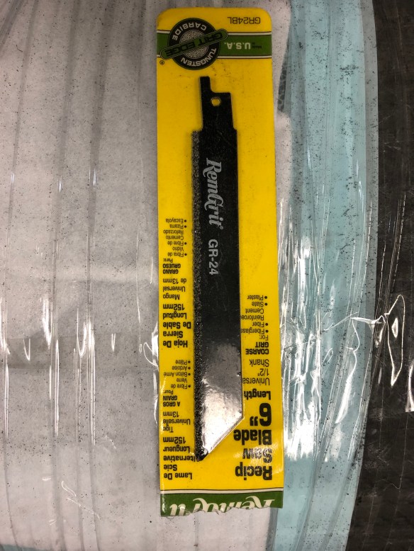
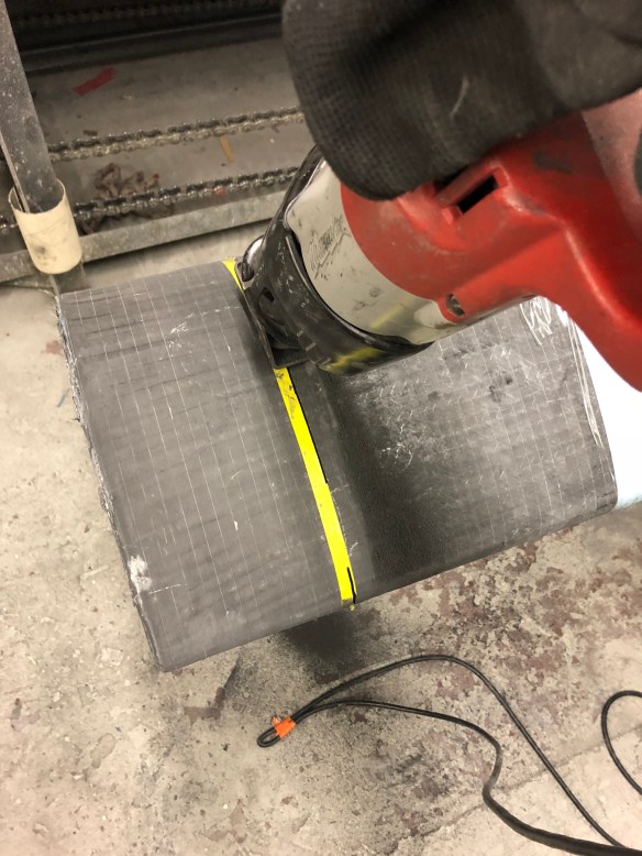
And because they’ve taught me with the Sawzall on carbon, I cut the three foot by 5/8″ precision main sheet slot in this thing today, including nice radius edging and line exit ramps. On Monday this boom is headed to this boat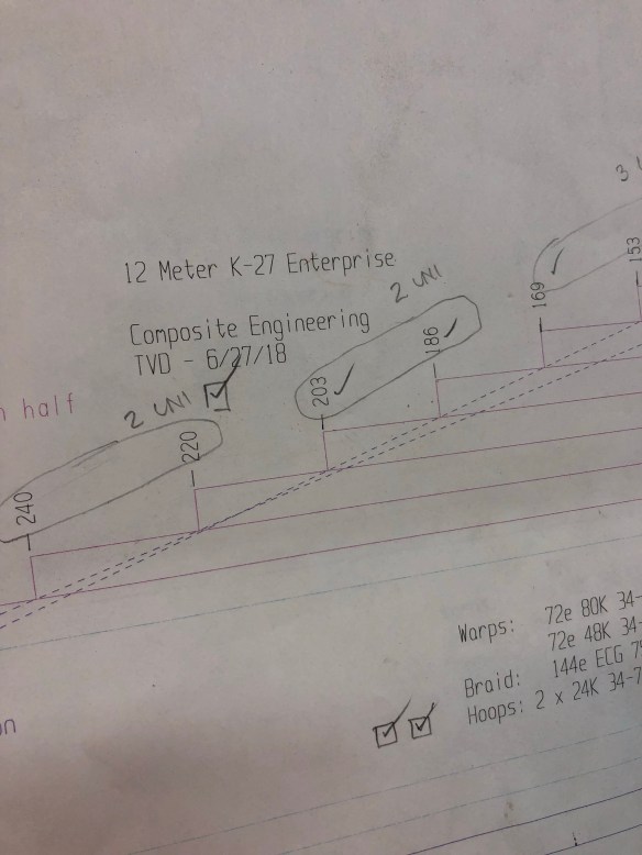 You can search it on Yachtworld where the description says the motivated seller has pumped $1.5mil in to Enterprise but will let her go to you for $800k. I didn’t know those numbers until AFTER taking the Sawzall to the thing. Whoa.
I put in about ten hours on that boom, all of which meant the top guy didn’t and he worked on our mast instead. Horse trading.
Tonight finished up at 9:30 with the first wave of carbon laminations on the primary hound. Photos on that maybe tomorrow.
Getting close – hopefully shooting on primer this Friday.
PS – Jim, I don’t think you need to fly out. I’m working a deal with a local boat builder to share a 53′ rail/truck container next week heading to Los Gatos rowing club and to our Richmond boat yard. So I’ll be flying home and hopefully we just open up the big box on the California end. Stay tuned…
 that’s a cardboard packaging strap formed into two handles and a drag section. Think “dragging the infield” after the third inning. You spread your fairing putty quickly, working it in to the surface with the spatula. I’m working with 175gram batches, which spreads out to about ten linear feet on one side of the mast. The drag tool evens out the filler and removes the spatula lines. Here’s a look at the first pass on the port side.


 there’s also some handwork shaping around these hardware areas.


 all Sat afternoon went in to fitting the mast foot. That included over 30 threaded taps for the 5/16″ screws, plus the 8 in the nose piece. Led to rather sore wrists. The foot is ready for final installation but Will asked me to wait until we get the lower terminals for the diamond wires sorted out.


 The pieces were wet out on the table, and because it’s thick, very high density braid, I literally mashed the epoxy in with my boot heels before laying it out over the mast.


 The boss inspected later in the day and was very happy with the lamination results. Gooseneck built – just needs fairing cleanup to go.
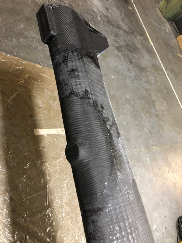 The nose plate (point where the standing rigging attaches) is made of three pieces of G10, bonded and screwed together before being bonded and screwed into the mast tube.


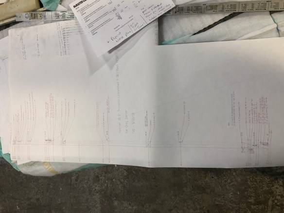

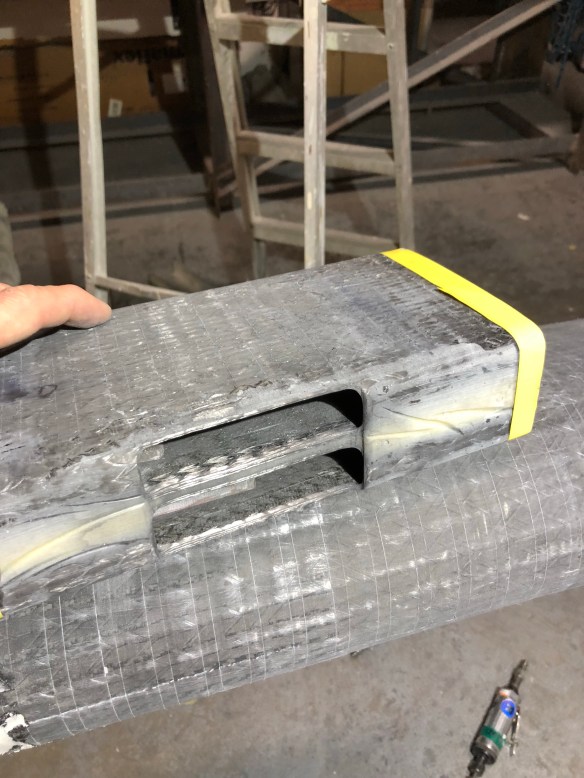
 this old sanding belt lined up edge to edge helps us translate specific height-on-mast points around the full spar. The fabric curve in that photo is an externally applied reinforcement of carbon braid for the jib halyard exit area (we add back around the slot), and it is fanned out like the you saw in the gooseneck.
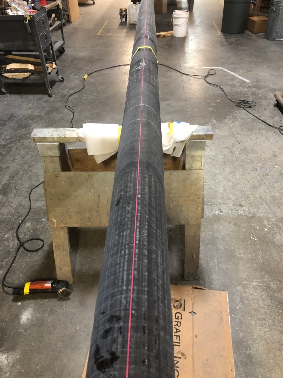 The slot was cut and cleaned with a drill, sawzall, router and small disk sander. The electrician’s fish tape was sent down from the new hole, and the part drawn up on a string.


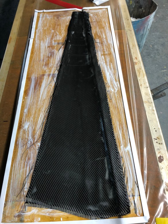
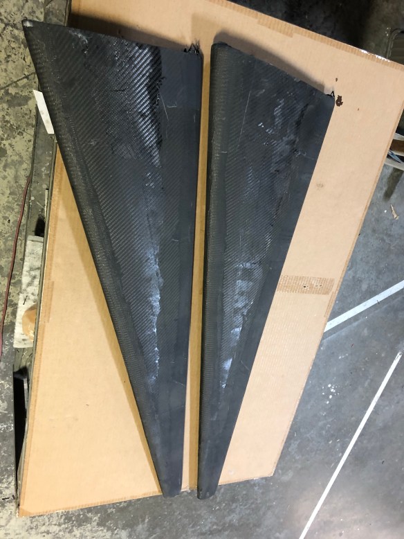
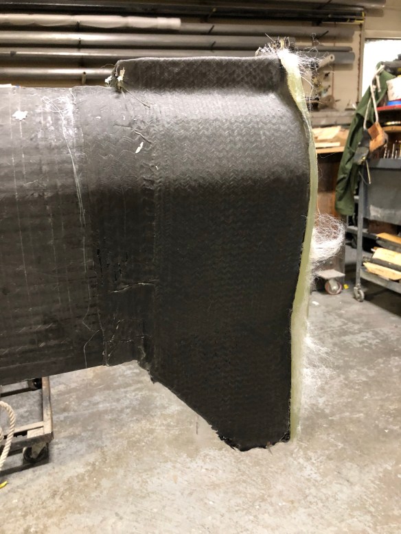
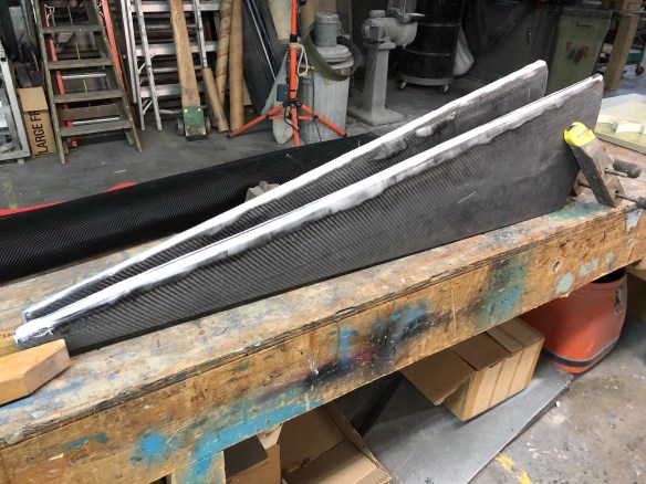
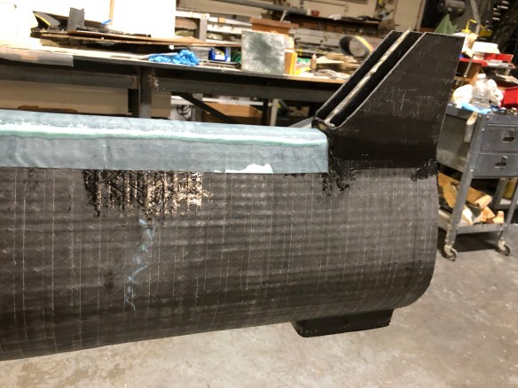
 For you fabricators reading this, I was impressed how these guys achieve resin saturation and excess absorption into the bleeder cloth by using pressure from tightly wrapped packing tape and clamps, where vacuum bagging is impractical. We are using this technique to apply the outer carbon reinforcements to the mast head, the gooseneck and six padeye bases along the mast. They also had me do that to the spreader trailing edge wraps last night. See them ‘bandaged up’ and then unwrapped below.




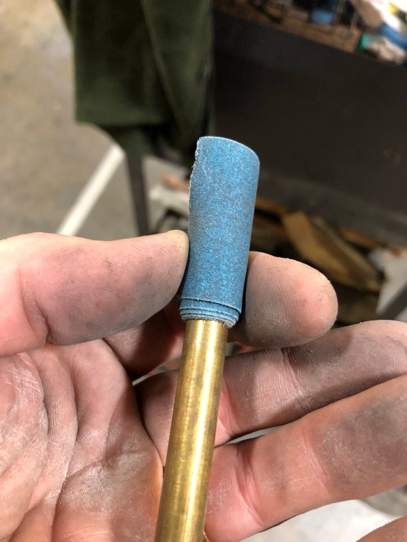
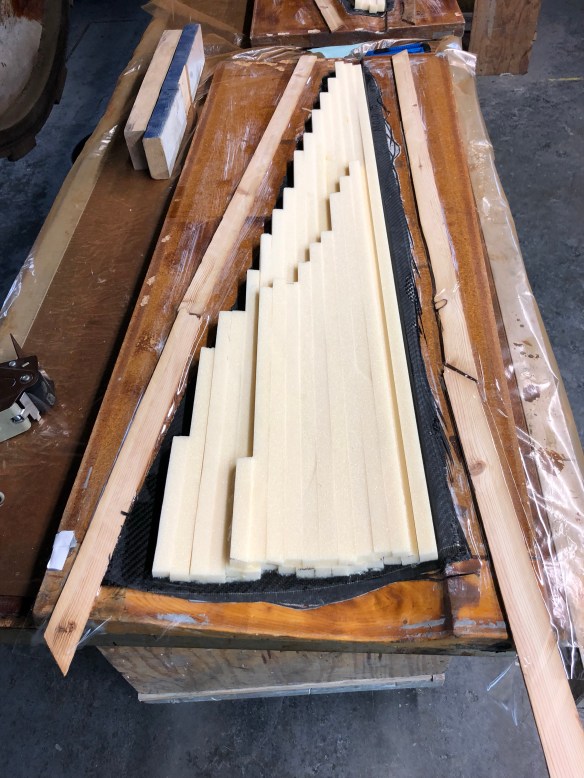
 ppThe foam core was bonded in then next-day trimmed down flush to the clamshell glue line. Here are two tools I used.


 after the band-saw rough in on those pucks, this tool was my shaping friend.