Very motivating…

… Seeing another builder’s boat get launched! Saturday was the first dip for Andy Miller’s F22, christened “Dart” at the Alameda crane launch pad.

20140904-110220.jpg

20140904-110242.jpg

20140904-110255.jpg
His project took about four years from purchasing the plans, with very impressive dedication in the off hours from his busy engineering career. It was fun watching Dart go through the build stages and it’s very inspiring to see the finished product – makes me want to get painting!

20140904-110747.jpg

20140904-110757.jpg
Dart floated well above her waterline (before we stacked 10+ humans aboard), the new engine fired right up, the beams unfolded perfectly, and the Ballenger rig looks fantastic. Andy has some used f24 sails to modify and use before making that one more big purchase. Can’t wait to get out sailing on this speedster :)
Great work, Captain Andy!

20140904-111104.jpg

Above the deck

This week we’re driving towards completion of big exterior pieces. First up is the windshield, which after much fussy fairing work is looking pretty good. Time was well spent making accurate patterns for the Tap Plastics people to cut the smoked acrylic windows.

20140902-144101.jpg
They are rebated in the frames so as to come out flush-mounted. We’ll try just bonding them in, but little blots could be added if needed later. The panes are stored now, awaiting the boat’s final painting.

20140902-144403.jpg

20140902-144423.jpg
Next up is the hard dodger roof which is in cardboard mockup now. Trying to find the right balance of minimal windage, being able to see over it standing at the tiller, not whacking one’s head going in/out of the cabin companionway, and not being an ugly blob. Oh, and not blocking the cabin top winches!

20140902-144854.jpg

20140902-144905.jpg

20140902-144924.jpg
That last photo also shows the new stern tower leg stubs getting faired in before the remove-able legs can be sleeved on. Here are the steps so far:

20140902-145159.jpg
PVC pipe at the center for a wiring conduit and foam core strips shaped to give it all some faux-wing contour. The two stubs were built whole, but I should have done one 30″ and cut it in half. Then we transfered a half-model of the shape and made a plug mold for the 48″ legs. I was pretty darned happy with this first molding project, but…

20140902-145630.jpg
In the photo you can see dimples in the panel; the vacuum was strong enough to collapse some unsupported wood in the mold. Argh – good learning that a plug must be SOLID.

So the mold got repaired and four leg-halves made just fine without bagging.

20140902-150032.jpg
Now we’ll join the two sides around some internal rib spacers.

20140902-150139.jpg

20140902-150154.jpg
These parts are set aside awaiting 24″ threaded rods that will get embedded in the legs, pass through the stubs and be bolted from inside the aft cabin.

20140902-150326.jpg
Ok, the box from McMaster Carr just arrived, so those long bolts can go in this afternoon. Then it’s time to design the top part of the tower for all the various gear.

It’s dark out there!

Captain Rick Holway is making sure the Carters have enough sailing miles before launching the new boat. He’s a veteran of the singlehanded sailing society’s solo Long Pacific races, so I pay close attention to his coaching. We picked a no-moon phase for an overnight sail in the gulf of the Farrallones last night.

20140825-212947.jpg
Outbound at dusk we were among 50+ salmon boats – the prospect of navigating thru that fleet then the northbound shipping lane in pitch black was daunting. So we headed east amongst the unmarked but rather boat-crushing rocks of the middle and north Farrallons.

Zoom in to the next photo and see the separate rocks in the distance – the chain extends for many miles north, with gaps plenty wide enough to pass between.

Throw in an inbound marine layer and by midnight the lack of stars and moon made the sea and sky one black blob. Made me think hard (between 1-4am) about being visually impaired and relying on autopilot vs windvane self steering and how they are mounted.
Ian Jones wrote in suggesting a wider stern tower for solar panels too.

20140825-215019.jpg
Good idea but it’s getting crowded up there and I don’t want the windage of panels that high – we’ll put those on top of the dodger and out on the beams. I need to widen the tower a bit and figure out how exactly to connect a tiller pilot that can control the new rudder’s trim tab, overriding the vane when the tiller pilot is connected. That’ll be for motoring and when steering to the compass heading is critical (as opposed to optimizing for wind angle with the vane system). And this 24 hour sail came just in time before building the tower legs Tuesday to make it taller and get that radar up well above the boom.

After going about 40 miles out, we got back to SE Farrallon in the early morning for Rick to spot four Albatross. Kind of a rare sighting there, and a nice little Puffin touched down near us to cap the day.

20140825-215822.jpg

20140825-215845.jpg

Is it an arch or a tower?

Looks like we have a basic shape in mind for the structure over the stern of the boat, even if we don’t know exactly what to call it. The tasks for this tower are 1. Place the wind vane self steering gear well up in to the airflow behind the mainsail, 2. Mount the radar dome, 3.mount the GPS antenna, 4. Provide the rearmost anchor point for the cockpit shade Bimini, 5. Hold a backup VHF antenna in a pinch. It has to be wide enough for the tiller to swing a proper arc, but can also be a limiter for keeping the rudder from slamming broadside out of control. We also want it to be a sturdy handhold for climbing those steps to/from the stern.

20140822-000839.jpg
So this is a cardboard mockup with legs of about four feet tall, raked back for looks but also to center the top platform where it best suits the wind vane. The width has been determined by the (arbitrary) placement of the previously made stairs, and the general idea for this thing has been in mind since first watching the Volvo Ocean Race boats a few years ago, with the little towers on their sterns to mount all the comms gear.

20140822-001331.jpg

20140822-001347.jpg

20140822-001358.jpg
And no, the real tiller won’t look anything like this ugly grey PVC pipe – that just did the tiller angle measuring role.
One wrinkle in the construction is that this tower will have to be remove able for the road trucking. So I think we’ll build 18-24 inch permanent stubs up from the deck, then sleeve the rest of the legs down over the stubs, with threaded rod inside to bolt the tower in from the aft cabin. Also need to figure out an internal conduit to easily hide all the wires from tower-mounted gear.

If anyone has any warnings, words of advice on stern towers, or info on the minimum suitable height above deck we can run the radar dome, please comment.

Engine bracket, part 2

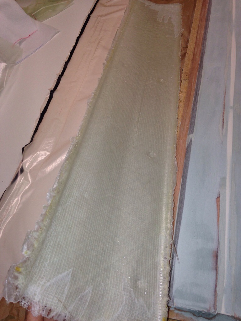
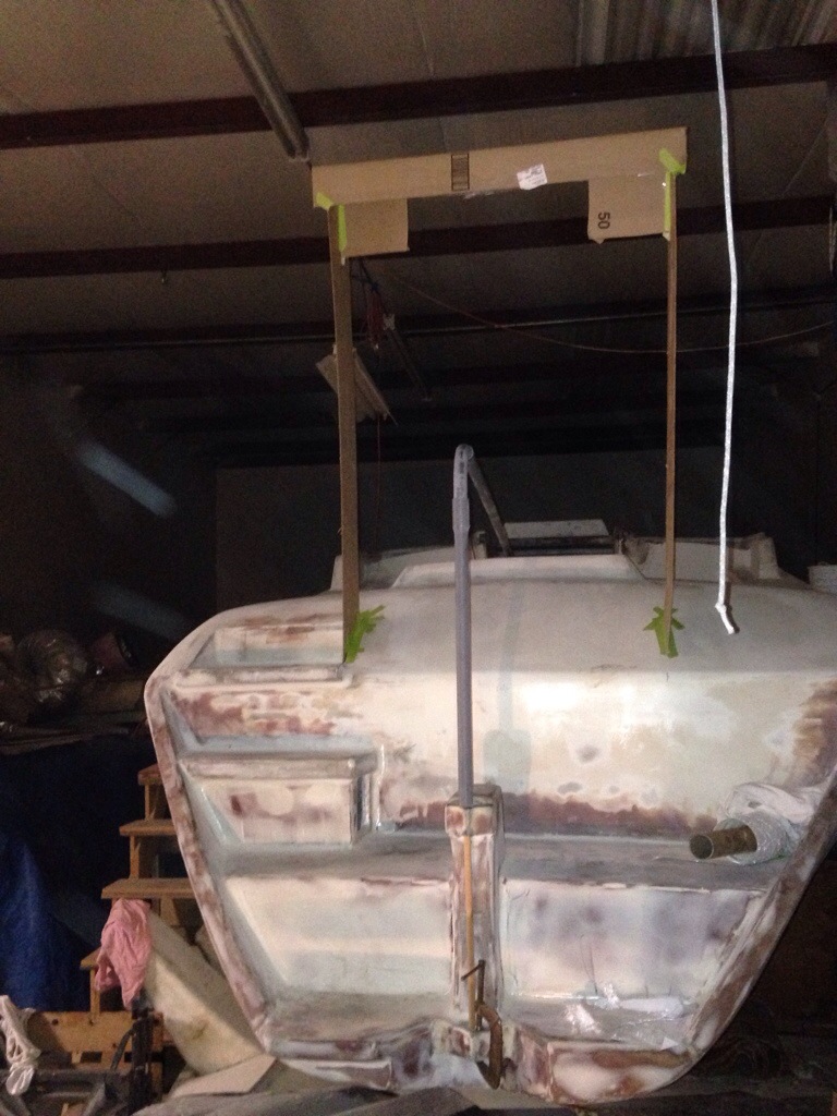
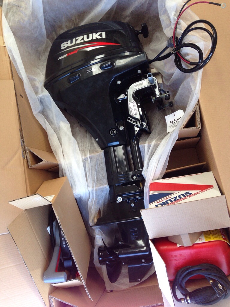
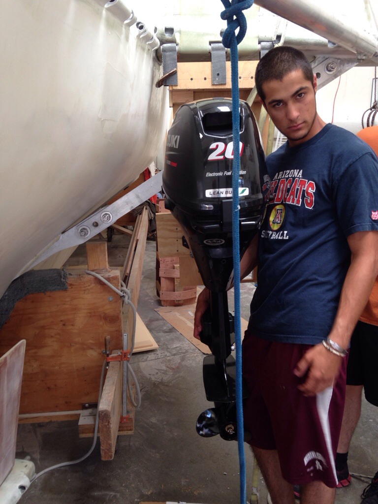
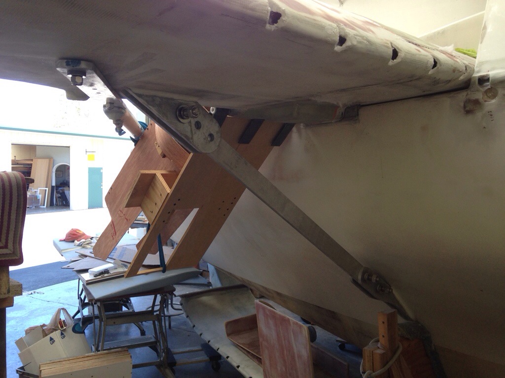
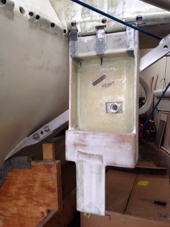
We advanced this project through the structural laminations and it came out nice and strong. The engine mounted up just fine, and titled up to the sailing position very well.

20140820-224748.jpg

20140820-224822.jpg

20140820-224901.jpg

20140820-224946.jpg
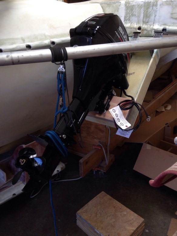
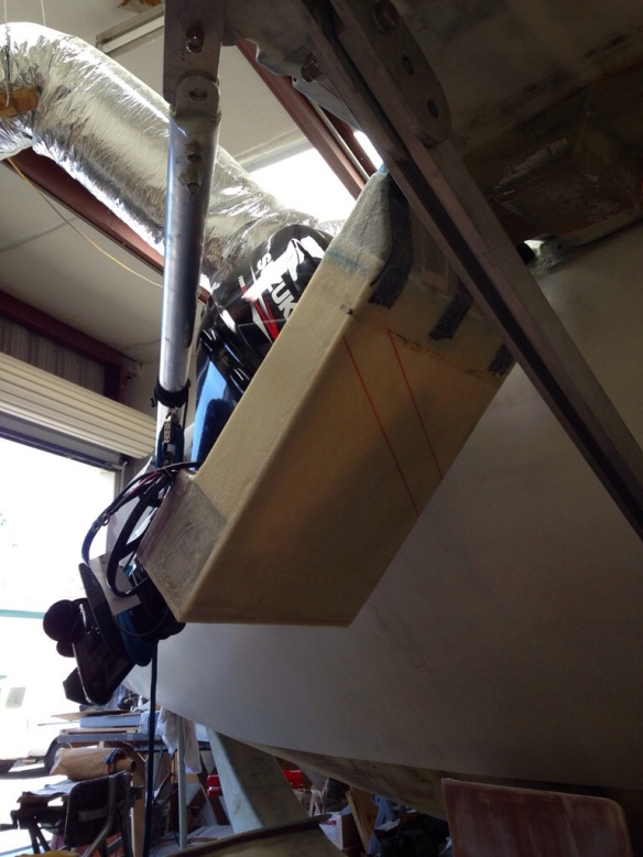
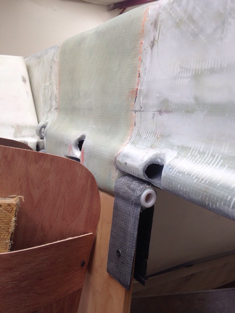
Once the motor was in place, Dad and I built a triangular wave-piercing shield for the motor leg, with the idea of protecting the vulnerable looking exposed transmission linkage (that you see 2/3 down the leg of almost all Japanese small & mid size outboards).

20140820-225229.jpg
The diagonally cut slot lines up with the pull starter cord of the engine. I suppose it could actually be done from a launched dinghy but not very realistic to pull start this thing from on deck. We’ll stick a rubber plug in there until it ever/never is needed.
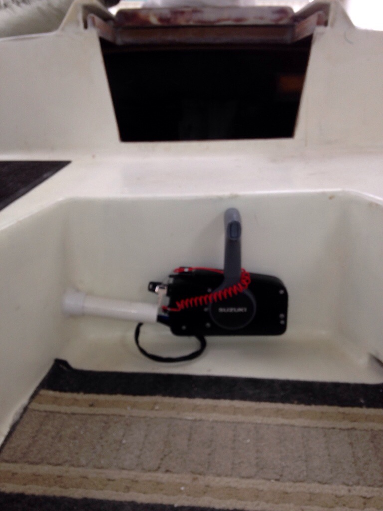
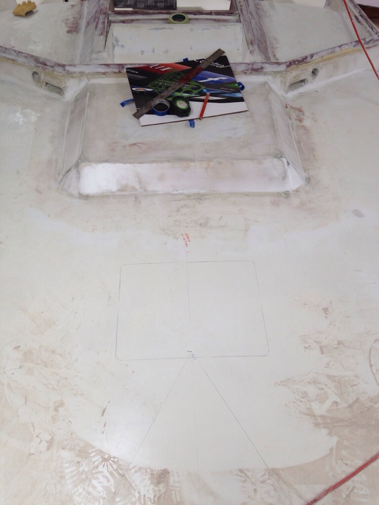
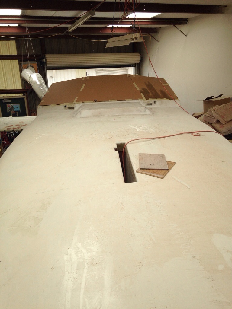
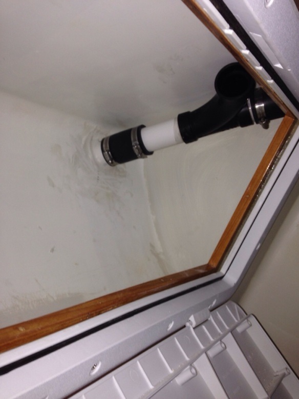
The final step was rigging the engine controls and a conduit tube from the cockpit through a corner of the aft cabin, the ceiling of the engine(less) room, through the emergency gear locker and out through the hull, forward of the beam far enough to make a gradual right hand turn to meet the motor. I like the controls here, in between the feet of the driver and not asking passengers to move their legs…

20140820-225540.jpg
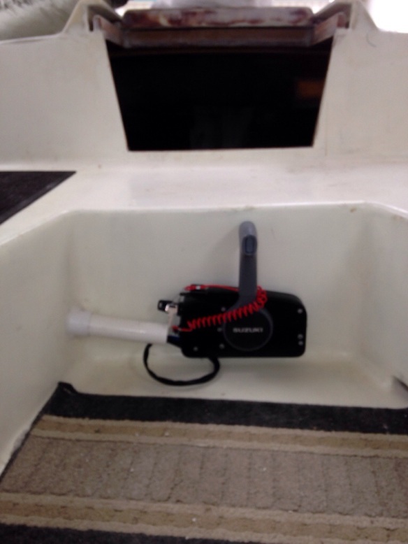
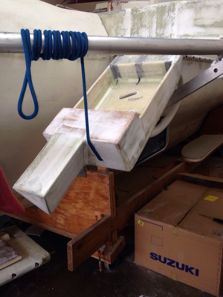
Now follow the conduit tube, made of Semi-flexible 1.5″ PVC “spa pipe”, from that corner by the Suzuki control box:

20140820-225709.jpg

20140820-225726.jpg

20140820-225738.jpg

20140820-225754.jpg
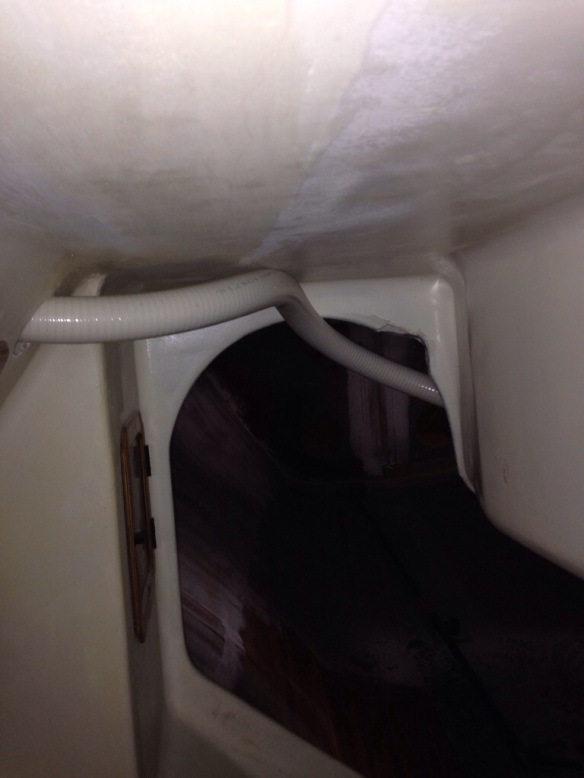
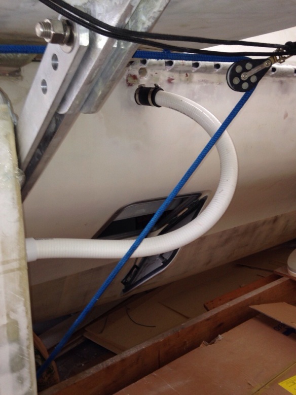
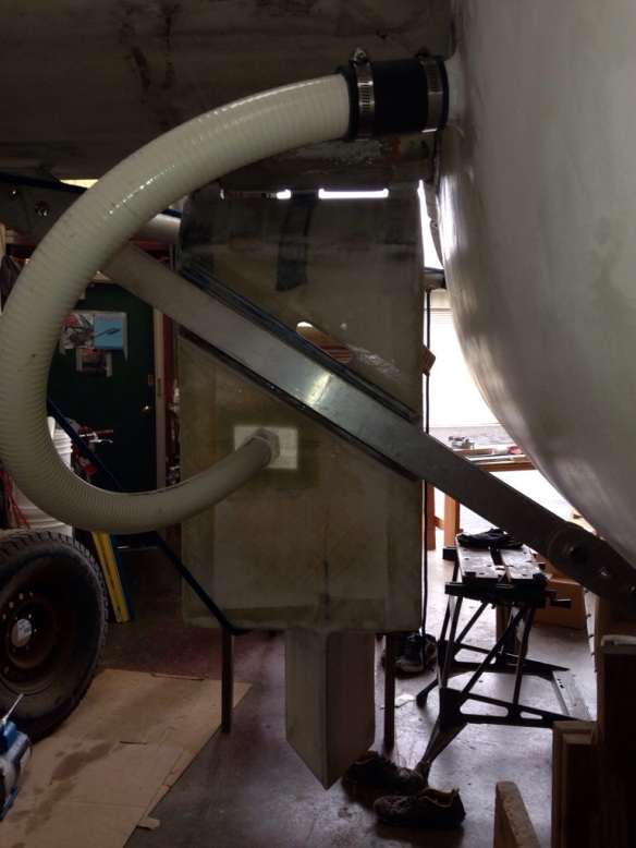
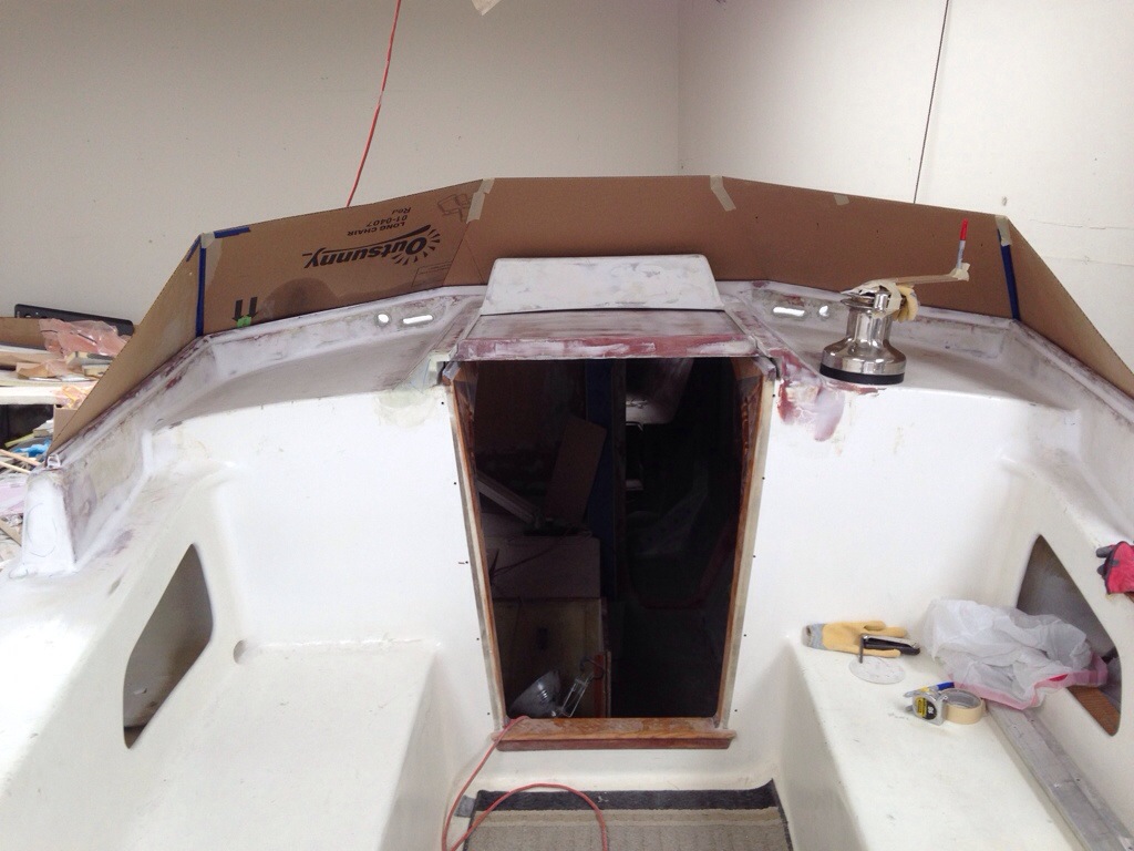
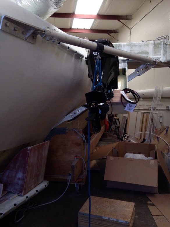
The black ‘Y’ inside the emergency gear locker will allow for a split in the rigging tunnel, with the gas line and battery wires heading forward in to the engine/equipment room and the shifter/throttle cables plus key start/electronics wires passing through to the cockpit. Outside the hull, there’s just enough flex in the white pipe to allow for the swinging of the whole engine bracket.
While that big white pipe is kind of ugly, it’ll be somewhat out of sight under the net and beam. Plus it will be a useful grab bar when approaching the grocery-loading chores thru the escape hatch from the dinghy.
Overall we’re very satisfied with how this all came out, especially since it’s a custom job taking inputs from various minds and boats. Thanks again Keith!

20140820-230350.jpg

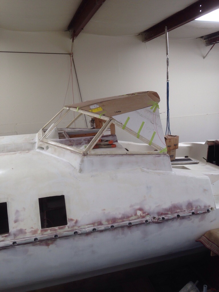
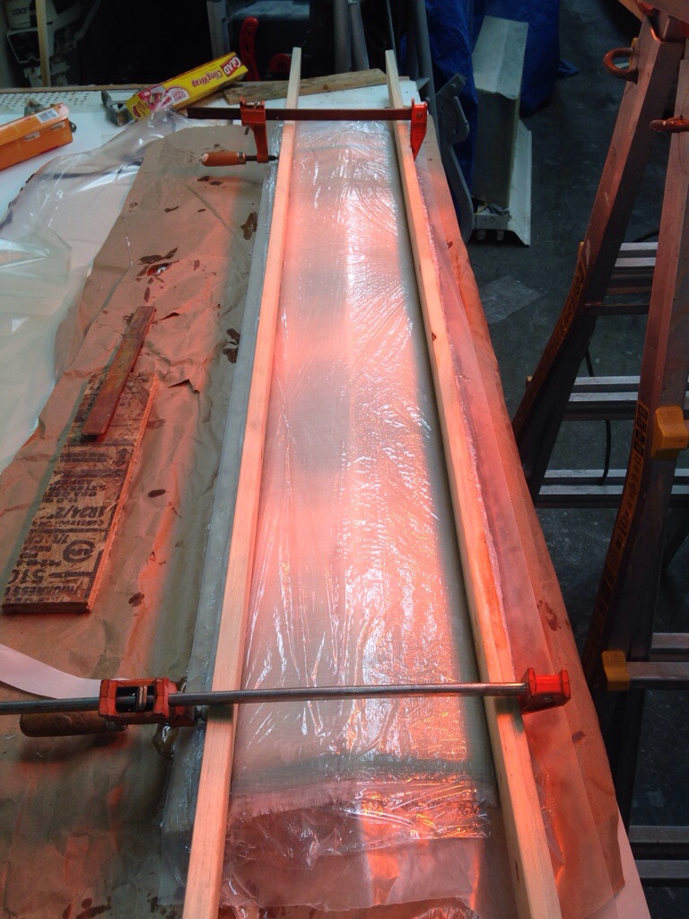
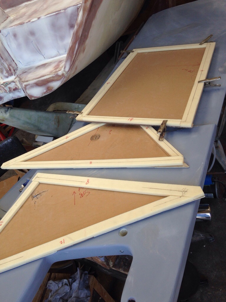
And today we got our heads around how to build the 8′ long bow sprit in carbon, instead of the sticker shock of “a grand” just to buy the carbon tube premade. Turns out it all starts with the concept of forming the new tube inside a mold pipe that has been split lengthwise, and blowing up a balloon bag from the inside once the materials are laid up in there and the pipe halves strapped together with clamps. This should be another interesting caper! Stay tuned for that one and meanwhile we’ll get back to the windshield tomorrow, making patterns for the acrylic window panels.

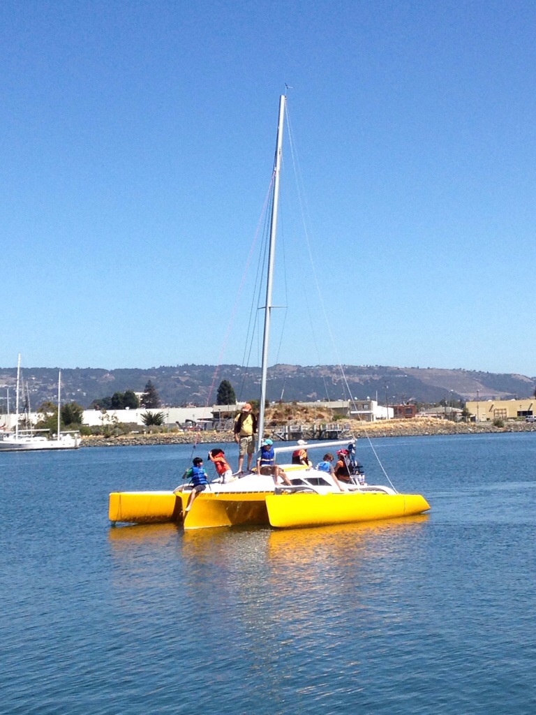
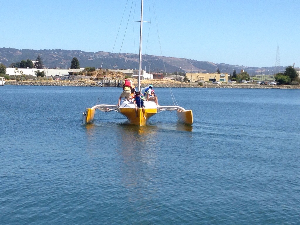
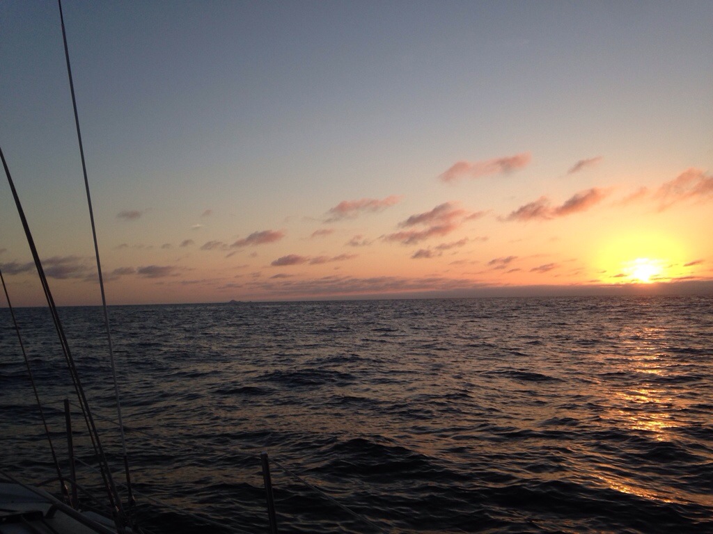
The shop closed at 3 today, just in time to get to the docks at Vallejo to crew for Charlie aboard F27 Tri Chi. It was like homecoming, as the boat was built just 2 months before Origami. We pounded thru BIG chop in San Pablo Bay, sailing fast to a nice 2nd place finish. Next time the chute goes up and the boat can win Vallejo beer cans! Nice driving Charlie :)

Engine mounting bracket underway

The wood mockup for sizing and positioning the engine has been measured and translated to structural parts. Everything is very light, except the solid hardwood actual “transom” piece cut from an old butcher block table. Sturdy and zero dollars – nice.

20140811-232520.jpg
Here you can see the basic shape; the bracket makes an inset box shape to keep the motor as far forward as possible under the beam.

20140811-232702.jpg
Getting the hinges on top securely attached seems a pretty big deal – do this wrong and the motor could fall in to the sea. So we’re doing lots of reinforcements underneath the foam triangle shaped cap.

20140811-232853.jpg

20140811-232906.jpg
This whole box shape is the structural part holding the motor. After it’s trial mounted later this week, we’ll add a wave-piercer / motor leg protector based on ideas from Keith Burrage’s lovely Skateaway tri back east. We all need to get a ride on that ship – the photos look fantastic!

The windshield frames are finally done and will get measured for the window inserts tomorrow. And the lazarette opening with a drip rail system went in today. More photos coming as those misc projects get finished. I was working on that main cabin skylight hatch base this afternoon when the Robin Williams news came over the radio. Seems like just a bit ago that Drew and I waved hello to him over burritos in Sausalito – so sad his torments ended a talented life at 63. Perhaps more sailing could have been a therapy :(

20140811-233934.jpg

Fits just fine

Thanks again for good counsel from Keith Burrage, Richard Woods and Mike Leneman on ‘going light’ with the engine. This is, after all, supposed to be a high performance sailboat. Today we received the 107lb Suzuki 20hp four stroke with fuel injection (no carb, Dad, so no repeats of fighting the old Evinrude on Lake Pinecrest!). Finally there’s a small EFI motor. And at $2,350 after rebate, with delivery and all the accessories included, this complete package is actually less than just the folding Gori prop needed for an inboard diesel. Wow, better sails ahead.

20140729-175619.jpg

20140729-175638.jpg
After many days of angst about this motor placement fit, it turned out great. The boys provided the muscle and we liked both the in-water position (waterline at the upper splash plate, prop nice and deep), and it stores up even higher than i wanted.

20140729-180531.jpg

20140729-180549.jpg
Now we can get started on the real bracket. Stay tuned.

While awaiting the motor it was time to pop a skylight in the living room.

20140729-180832.jpg

20140729-180846.jpg
This hatch fits under the boom, away enough from the mast rotator arms, and is oriented to draw the breeze in to the main cabin while underway or anchored in to the wind. Also good for sighting the main pretty much over the sea berth. Seems a nice extra bit.

Motor mock up

The new hinge design looks good – nice and clean up under the beam. Had to use a wood dowel on place of the real steel hinge pin because the metal wouldn’t quite fit past the neighboring brace structure. Must remember to put the real pin in BEFORE mounting the beam to the boat at launch time!

20140722-223737.jpg

So here’s the basic idea of the engine position. I’ve only seen this placement on Humdinger (the Walter Green tri that’s just now finishing the PAC Cup) and photos of the big boat VirginFire in the Caribbean.

20140722-223943.jpg

The real trick here is to see if there’s really enough vertical lift room to raise the motor enough under / next to the aft beam brace pole. This wood mock up has the prop fin 13″ above the waterline, much like we sail with the F27 motor tilted up. I need to find a real 20-25hp motor this week to judge how much the engine cover tapers in – thats the part that will hit the brace at the top. Really hoping this all fits as ell as I’m eyeballing it!

20140722-224259.jpg

20140722-224312.jpg

PS – the windshield frames are coming along nicely. Probably will have Tap Plastics custom cut and bevel edge the smoked acrylic from templates. Worth paying their cutting fees it seems.

Motor mount hinge change

Oops, those custom hinge brackets to mount on the cross-beam turned out to place the hinge pin a couple of inches too far aft. So that’s two very strong but very useless parts for the bin. Took a new approach today tucking the hinge up under the net lashing tube, and building it all in place. The green piece is the G10 hinge tube, held in place by thick, fiberous epoxy putty.

20140721-231348.jpg
The wood piece is a hardwood backing plate to help carry the motor’s force in to the beam. This new piece is adjoining the existing hardwood block that is the beam-to-hull anti compression pad.
Had to devise our own laminate schedule, so for the permanent record the hinge tube is held to the beam with two layers of 12oz uni glass, two layers of 12oz bidirectional and one layer of 45/45 double bias 17oz. All five layers wrap 48 inches long, reaching well out on the the beam fairing piece both top and bottom. Seems really comprehensive to me, but if any experienced builders reading this think otherwise, please holler. Thanks

20140721-232029.jpg

Apologies made

We closed up the shop early Thursday to make the parents evening at Griffin’s baseball camp. It’s hosted by Dusty Baker who actually attended this time because he’s not managing the Cincinnati Reds this summer. Griff had a strong camp and won a batting award, and I got to shake Dusty’s hand and apologize for cold nights at Candlestick in the 70’s when I wished he would strike out (as a Dodger). His reply was, “and I didn’t, did I” with a sly smile.

20140718-184621.jpg
Ok, it was a couple of months back that the windshield base grew up out of the deck. Yesterday the removable windshield got mocked up in cardboard.

20140718-184919.jpg

20140718-184935.jpg

20140718-184949.jpg

20140718-185007.jpg
The windshield should provide a lot of protection from nasty SFBay slop spray, and it’s intentionally wide to really enclose the cockpit once the hard dodger and cloth Bimini are fitted. A lot of modern boats are doing nice rounded / curved spray hoods, but I think this look serves the original Farrier intentions and it’s much more realistic to build quickly and cleanly.

20140718-185617.jpg
The cardboard became templates for the five panel frames, and we cut a 3/4″ wide router pass around the outer facings to allow 1/4″ deep acrylic windows to flush mount in the frames. Expecting the windows can simply be glued in, using some of the amazing new bonding products. Also, the middle panel will be built with a hinge on top so that window can swing forward to allow a breeze to pass through (thinking ahead to the tropics – thanks Geoff!)

The frames are corner-glued now and once that sets up we’ll vacuum bag each panel’s laminations this weekend.