Some days the boat kicks your butt

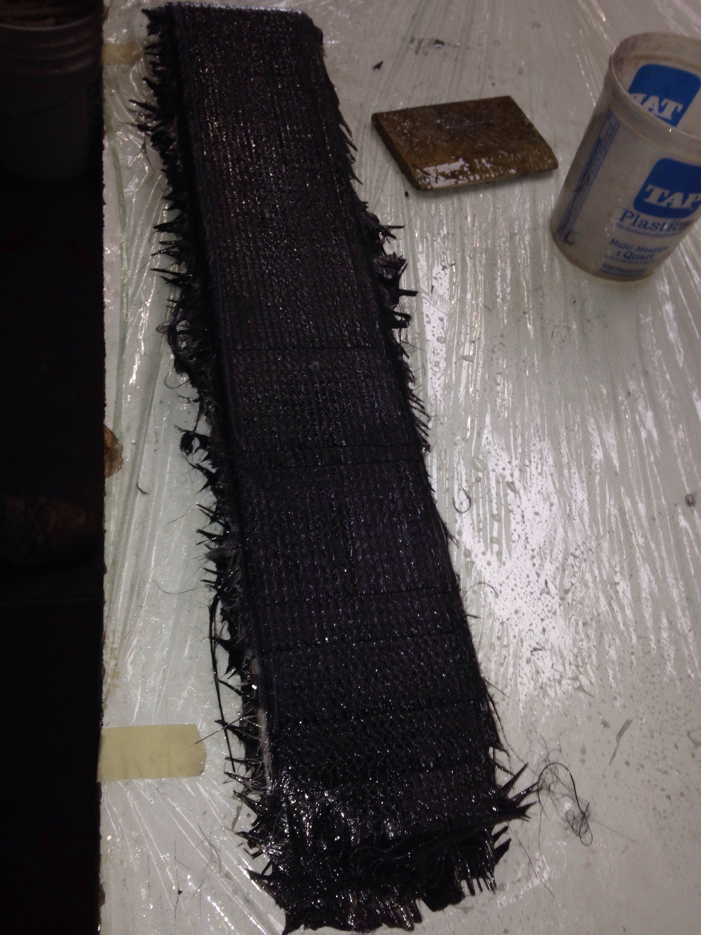
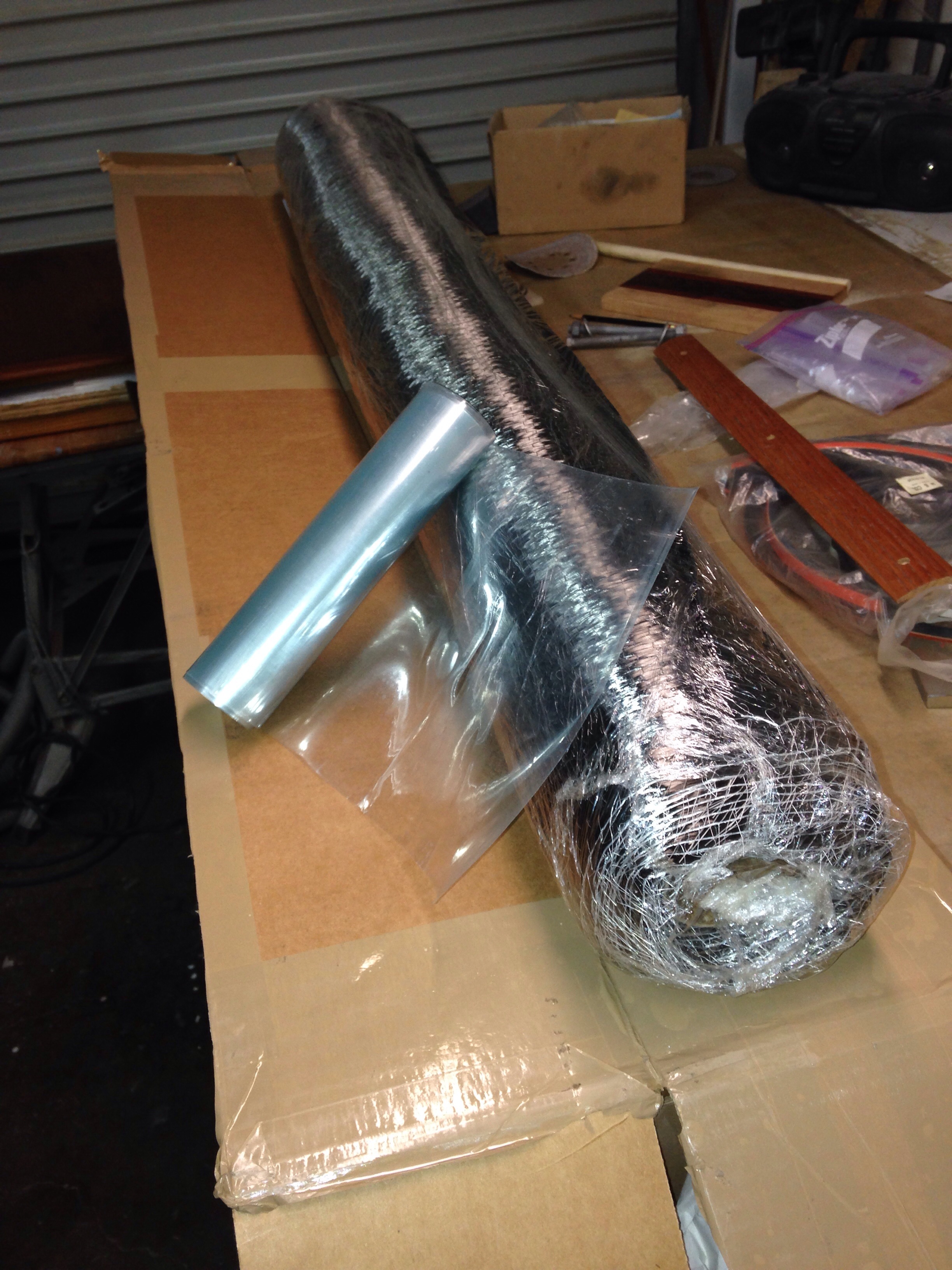
This little pile of fiberglass fabric doesn’t look so bad, right? It started the day headed in to the floats to glass in the chainplates.

20150304-190732.jpg
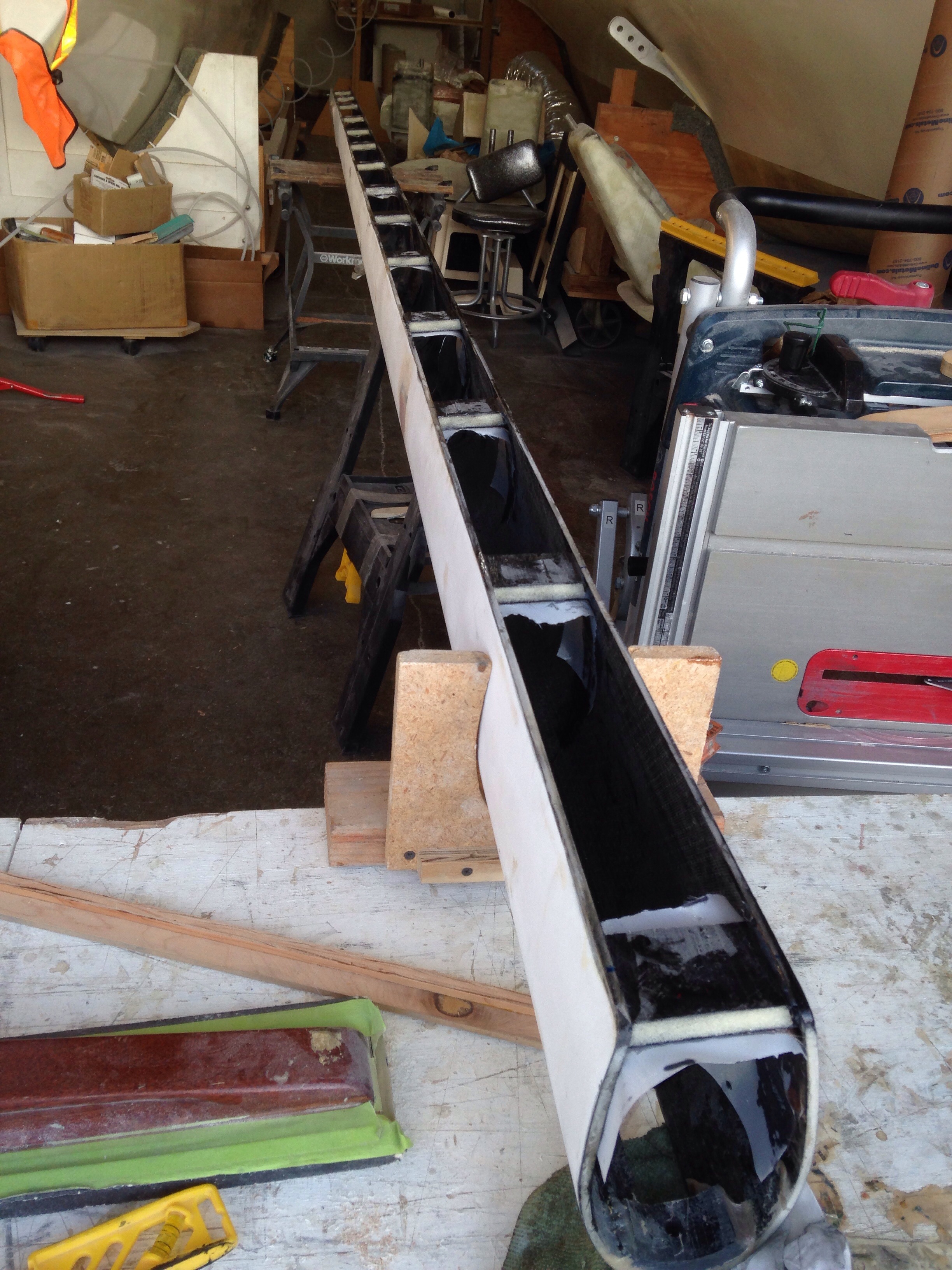
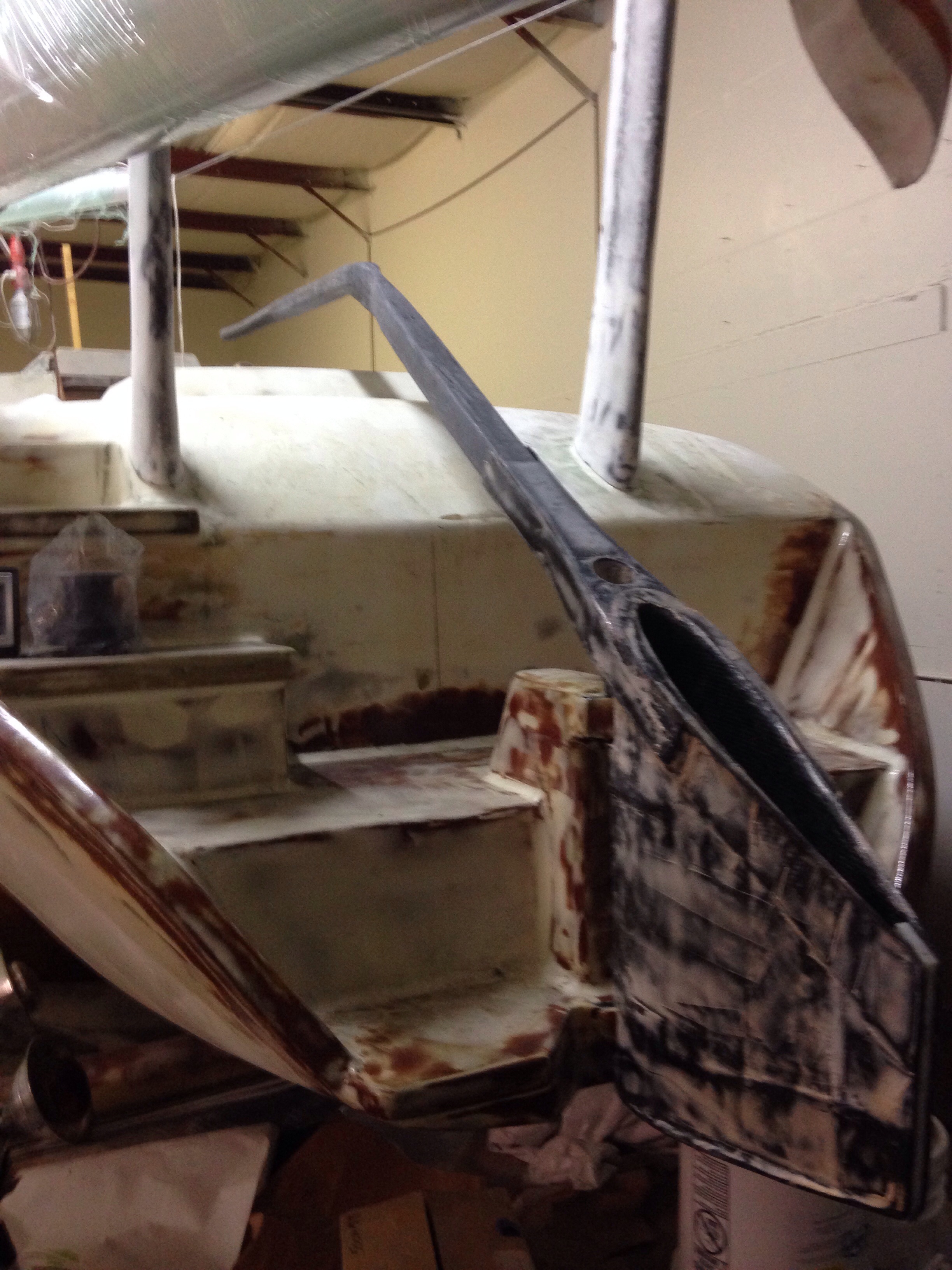
But crawling around inside these outer float hulls in the dark with no soles (floors) and stoop over headroom makes for a challenging day. The builder gets to do a circus acrobat move to get thru the bulkhead opening seen in this shot.

20150304-191029.jpg
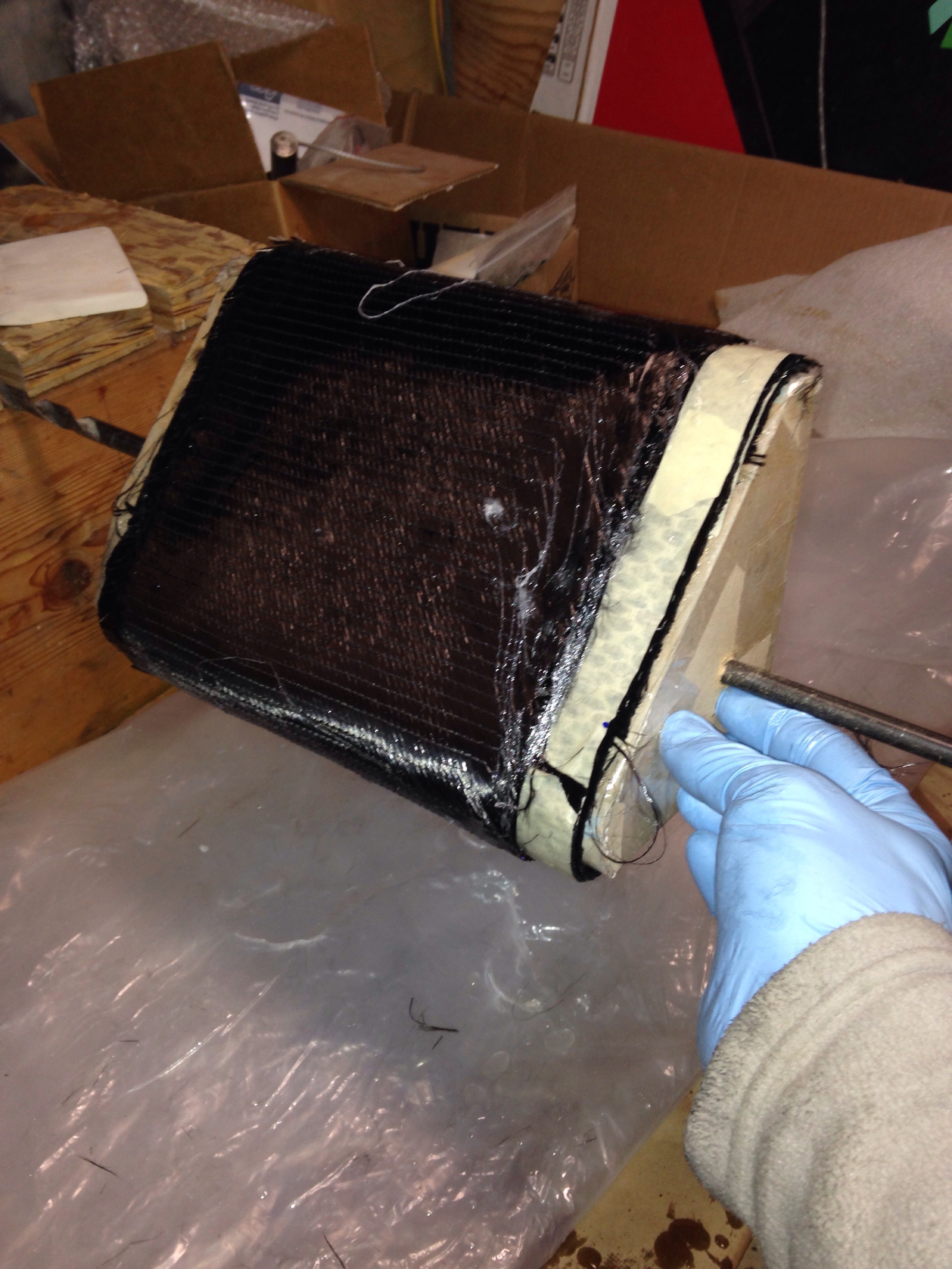
These lamps got the air temp to about 120 and the radiant heat was well in to the 160 range without trying to put this 35′ boat in to that auto paint booth we saw the other day! So it’s a localized heat post curing process inside the floats. The other side is under the lamps as this is written, with a sore back and various bruises. Boat bit back a little today, but she now has very strong anchor points for the 50′ mast.
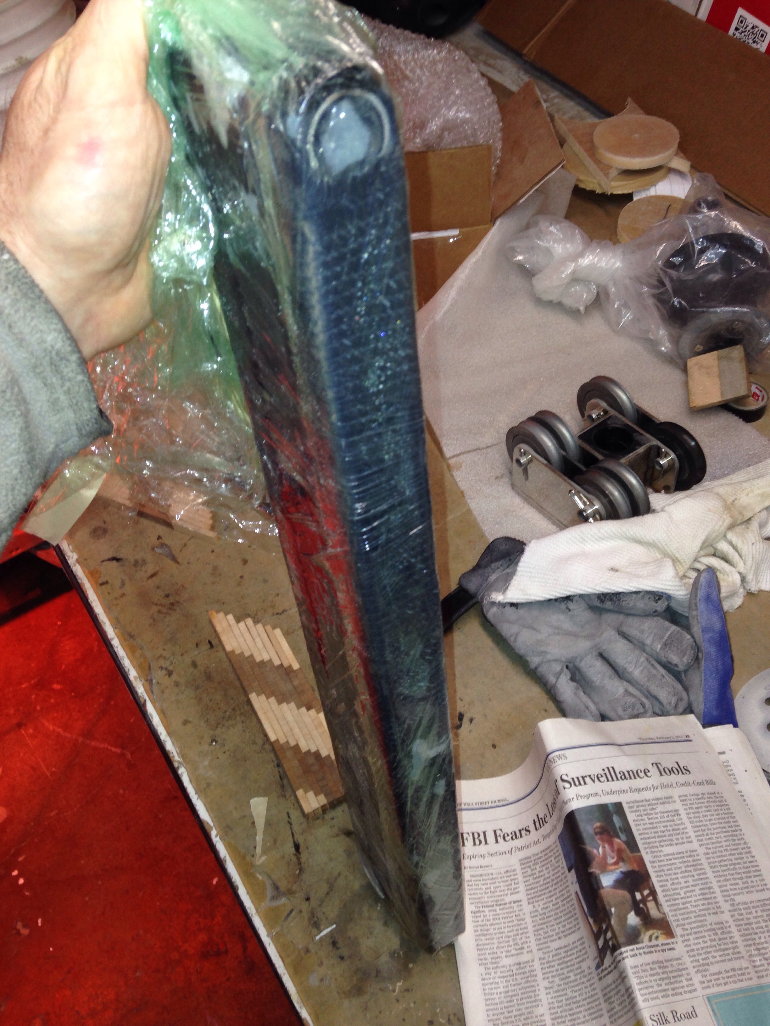
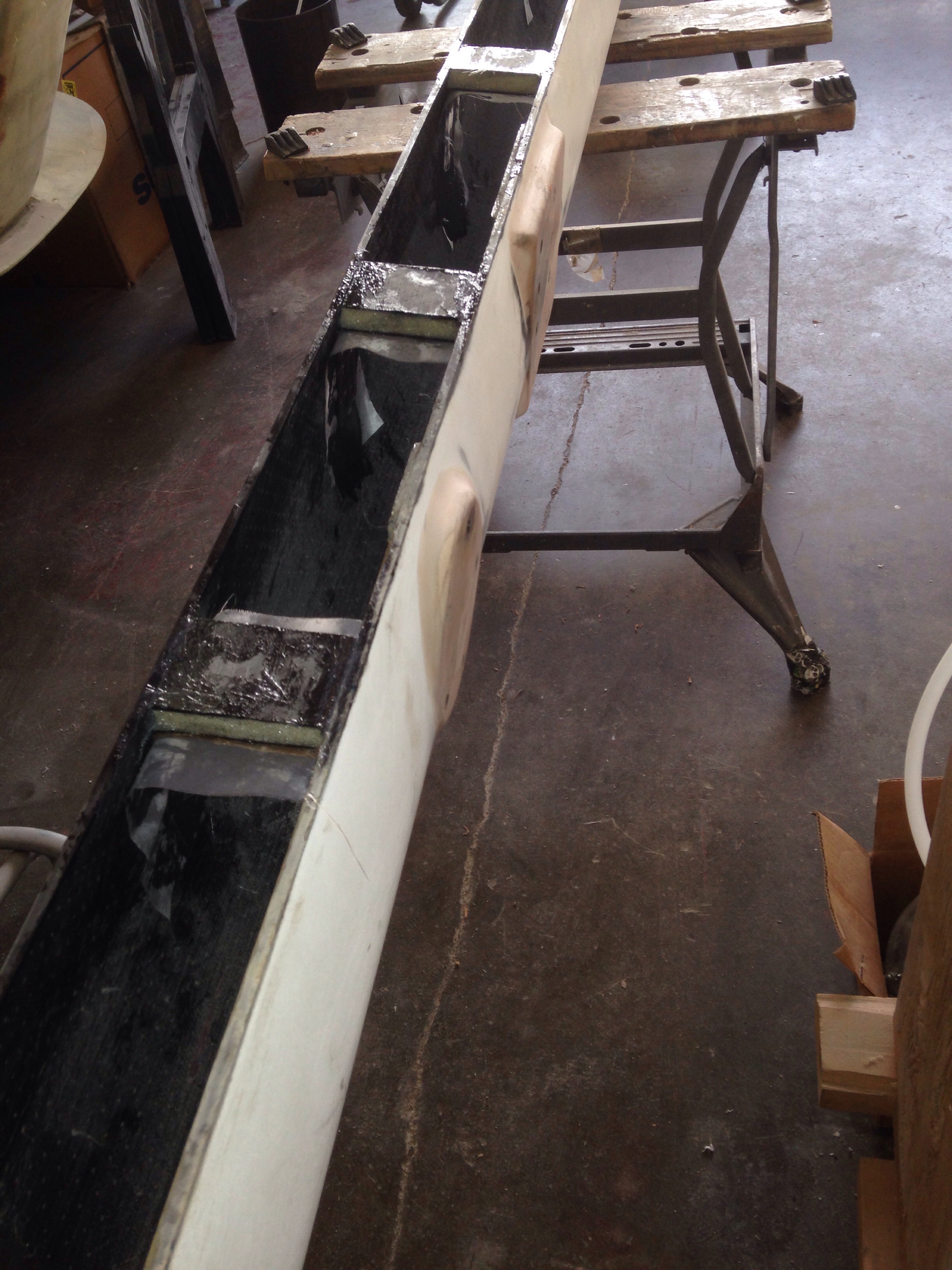
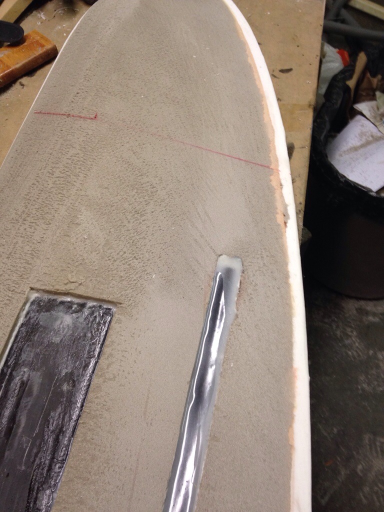
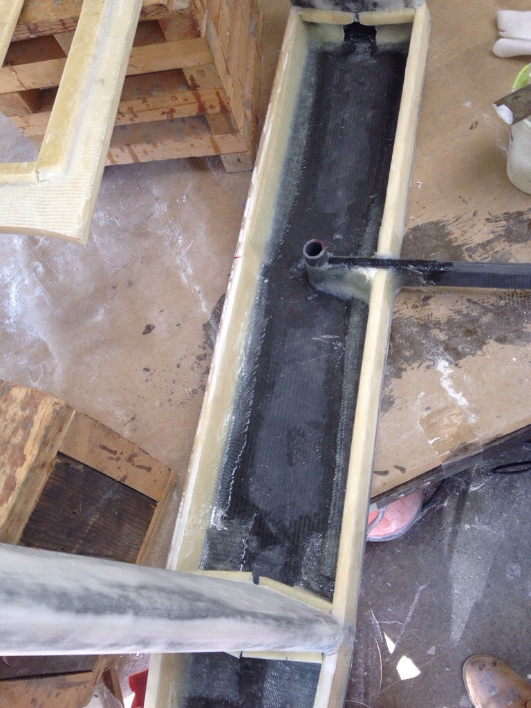
Here’s that finished chainplate from forward, facing aft:

20150304-191447.jpg
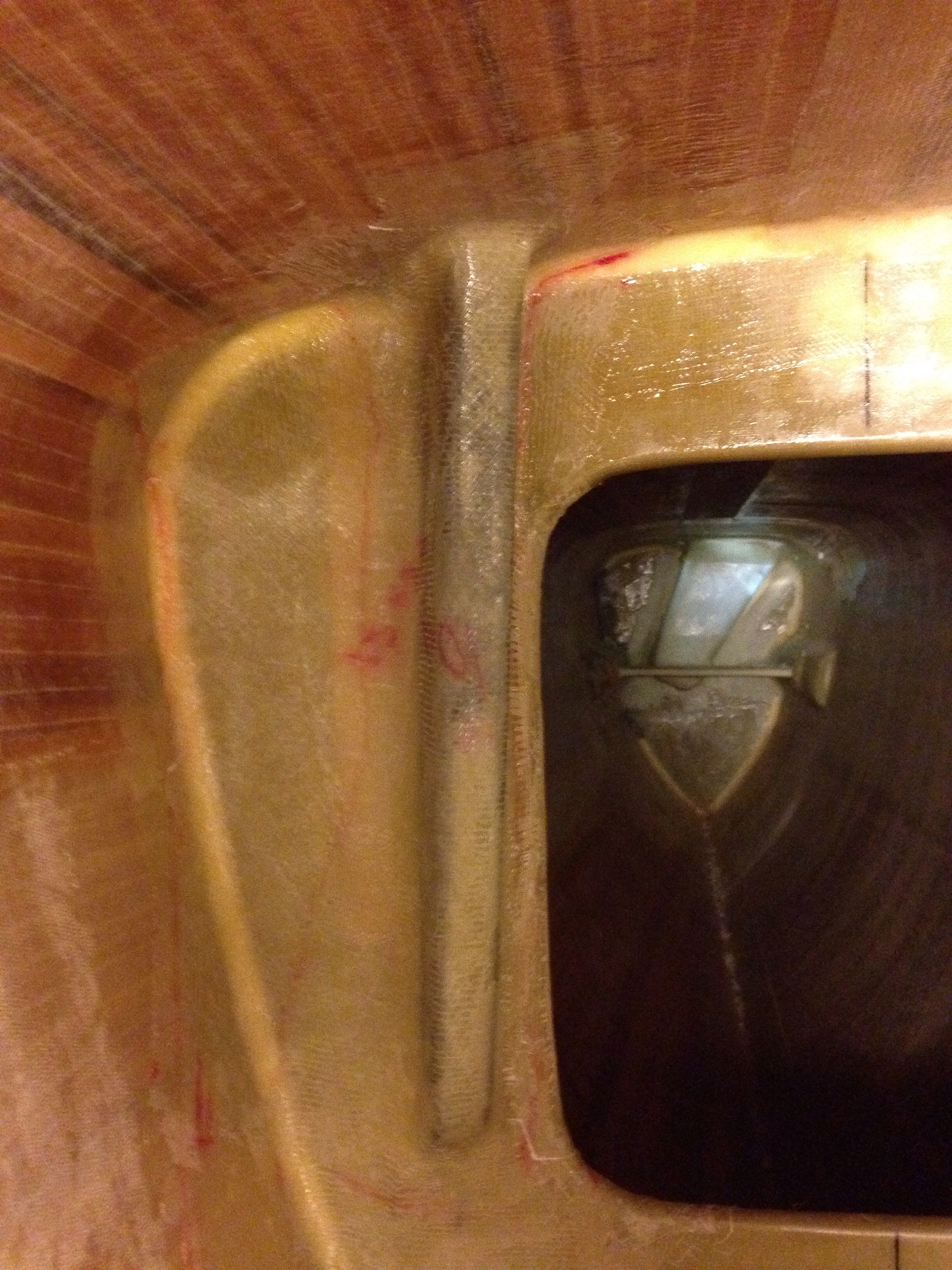
And from aft, looking forward. The glass looks a bit green in these photos – that’s the look of the resin still in curing / hardening mode. In a few days it will go basically colorless.

20150304-191542.jpg
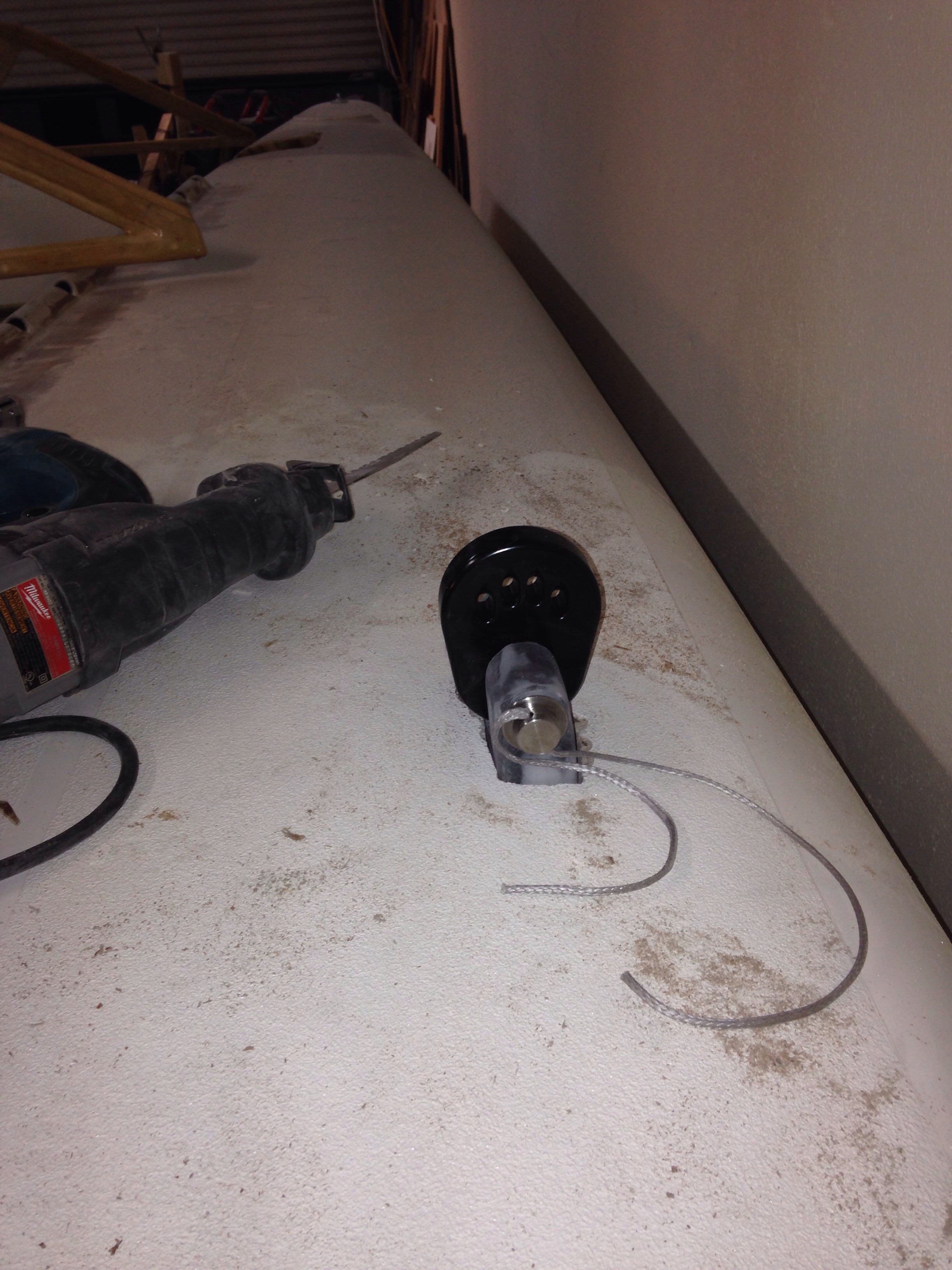
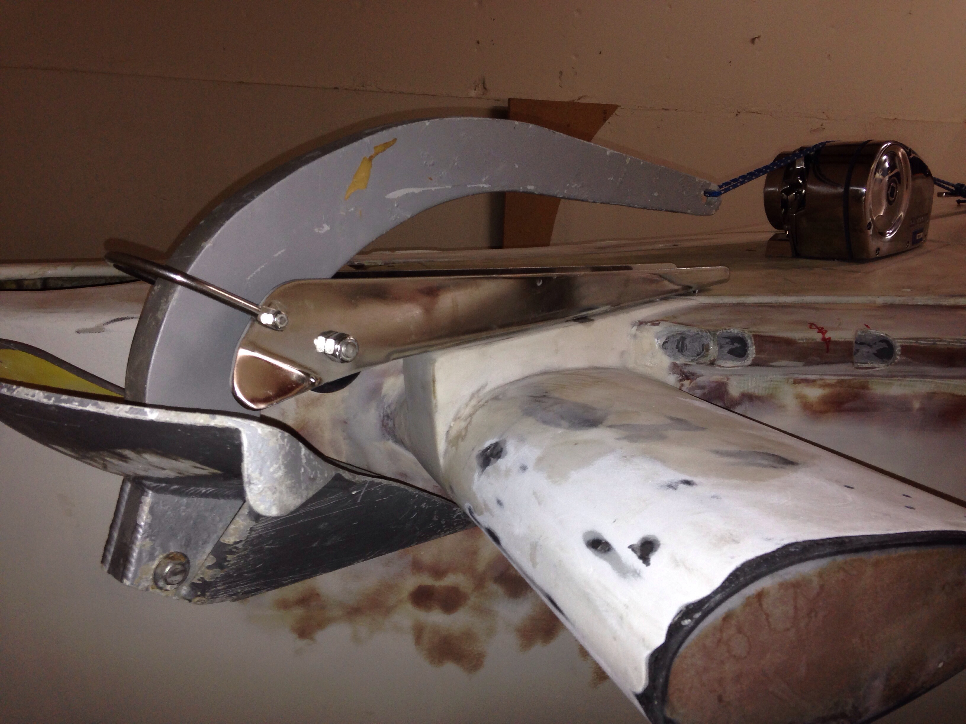
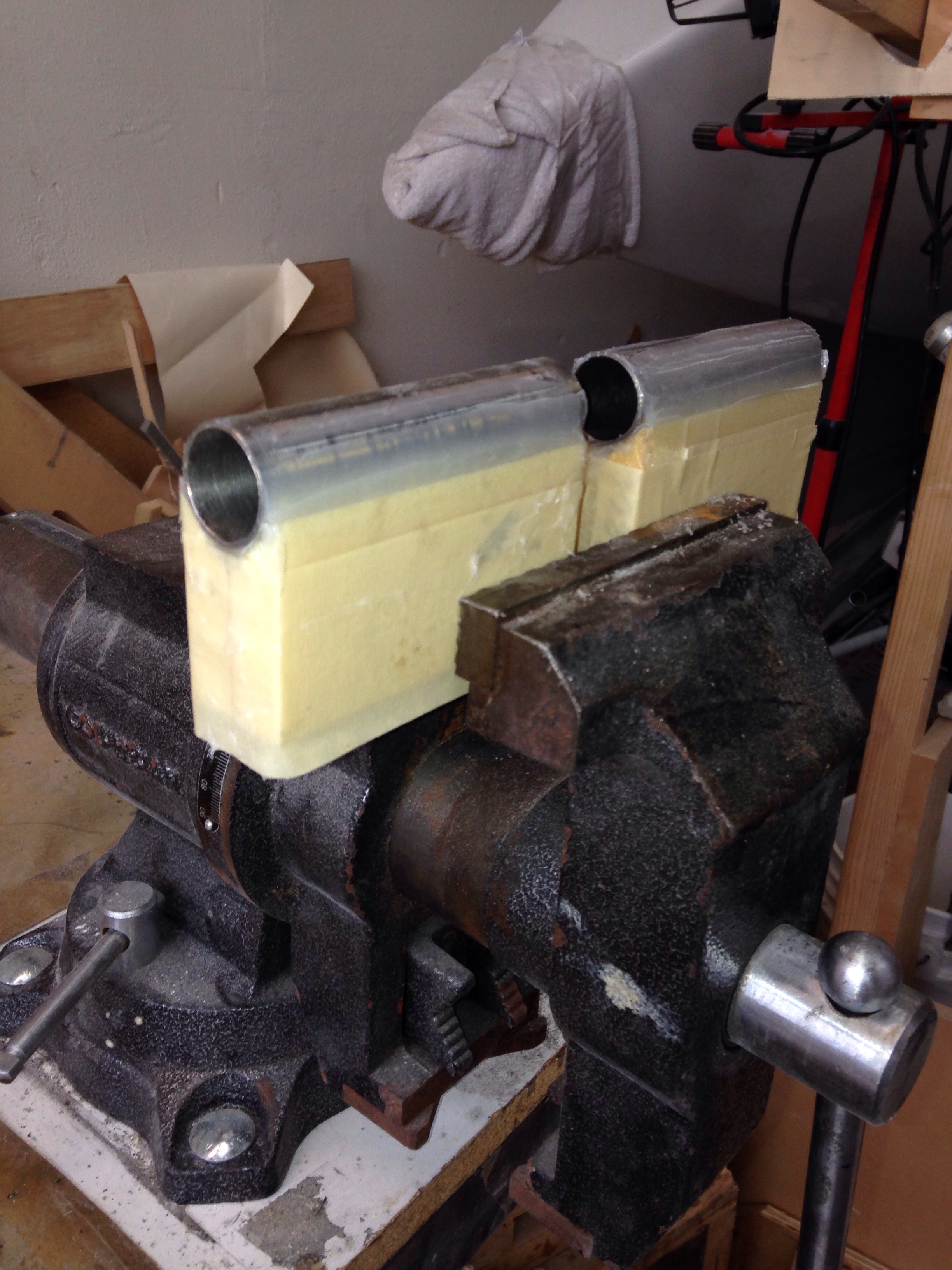
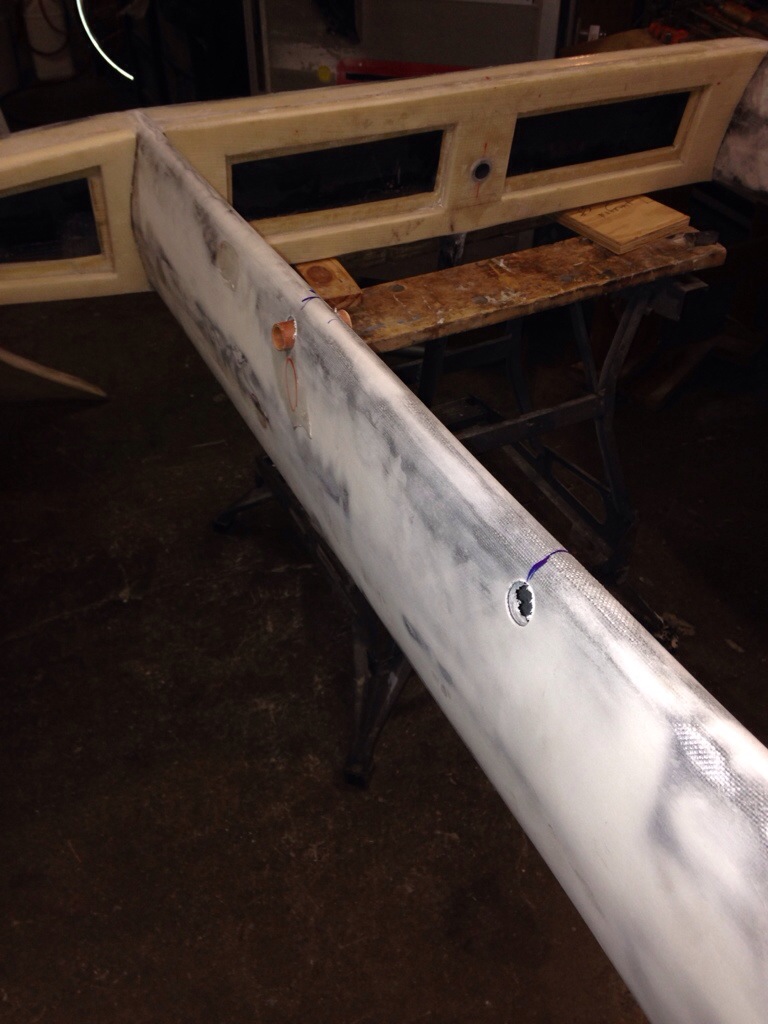
Five days of work, and all most people will ever see are these innocuous little stubs on deck:

20150304-191643.jpg
With a bit of shaping around the base, the Colligo “Terminators” fit right in. The last step is some lightweight finish glass cloth around the fitting up on deck – that’s a tiny job in the scheme of this project, so we’re pretty relieved tonight.

20150304-191852.jpg
Looking over the master to-do list, seems we’ve past the milestone of completing major structural builds. The chainplates had been looming, and the rest is non-load bearing / furniture type stuff, then fairing,sanding and prepping for paint.

The purchase order for the sails went in this week. They should be built during March, and delivered before the boat is launched. Keith Burrage of Skateaway Designs and I have gone over the measurements many times and he’s got a really exciting sail plan for the boat. This is so much better than the earlier assumption that we had to launch first with used crappy Craigslist sails and wait months before a sailmaker came to the new boat, took measures and went away to build. Instead, the drawing is done and we’re ahead of the loft rush during winter for Maine Sailing Partners. We even get to pick three colors for the radial cut Reacher! Jeanne, get the colored pens out for options…

Who had an EasyBake oven?

I remember the TV commercials, but never actually saw one. Did people eat the cookies that came from those things, ’cause I’m wondering if they ever got hot enough to actually cook? Turns out an automotive paint booth goes up to about 175degrees max; our epoxy can be post-cured at 70 degrees F for a week, or 3 hours at160 degrees. A while back we decided all low/no stress parts, like interior furniture or hull fairing, would simply cure ambiently during the warm weather. Recall last year we made a big Sheetrock box and a dozen heat lamps to cure the beams. It was a big pain in the rear but worked ok. Of course that box ended up 6″ too small for the daggerboard, and I was grumping about. Neighbor John with the exceptionally restored ’66 corvette asked why I didn’t just take the stuff to Harry the car painter? “He knows how to deal with fiberglass…”
The Sheetrock box went away and over a year we built a pile of stuff for the curing oven, capped off by the chainplates. Today was the day for PrismaCar’s paint booth.

20150302-230033.jpg

20150302-230053.jpg
For our records, the booth ran 3 hours at 170 degrees to cure the dagger, both rudders, all steering parts, chainplates, mainsheet anchors, windshield, hardtop, boarding ladder, stern tower, windlass platform and boom end insert.
Thanks to owner Harry Strouse for the $50/hr cash rate – worked out well for both of us. And the shop guys were amused by having to move a car out of the booth for these weird boat parts.

After the field trip, the chainplates went directly to their new homes. Here they’re wedged / suspended in position with some of the bedding compound applied. Tomorrow will be the rest of the filleting and maybe the glass work.

20150302-230627.jpg

Deck hardware continues to be test fitted, then all holes over drilled and re packed with epoxy putty, hardware final fitted then removed for the paint job. But there are a few permanent mount metal and carbon pieces that will get painted in place. Today we bonded on (and bolted) the receiver points for the aft beam triangle braces. These were a lovely aluminum welding job done nearby. Yesterday the pieces were chemically etched with the West Systems aluminum prep (a two part easy to use ten minute job – buy the small size as it goes a long way) then coated in clear epoxy. They were dry and ready for bonding today.

20150302-231156.jpg
The window cutout made it an easy-reach one person job to tighten the bolts. That was just coincidence, not swell planning.

And at days end we “paid” for half the morning bake by figuring out to eliminate some hardware up on the bow – we’ll see how that turns out tomorrow.

More of anchoring stuff down

Seems to be a theme around here right now – make sturdy bases for the sail rigging. This takes many forms.

Keith pointed out that the cap shroud chainplates as shown last week really should be swiveled 20 degrees off the centerline so the pull against the big clevis pin would be directly in line with the mast. He’s right, and this is another small improvement modification beyond the decade-old F39 plans.
Cutting that bulkhead slot was tricky last week, but a $2 short blade for the sawzall made the extra 20 degree slice easy.

20150301-205111.jpg
So now the plates fit at the new angle.

20150301-205207.jpg

Next up is a place to attach the twin mainsheets. Remember these are arranged in an inverted Vee off the boom, eliminating a traditional traveller. So we want the lower mainsheet blocks far outboard for good sail control. Again, not in the plans so we thought up this:
Big sturdy triangles glued and bolted to the hull side. First make a mold for the carbon fiber layup:

20150301-205514.jpg
The rod made it easy to rotate the piece as ten layers of various fabric orientations went on. This thing should be plenty strong.

20150301-205621.jpg
It was cut in two, and the form knocked away after this next photo. Tomorrow morning it joins the other pieces headed for the post-cure oven.

20150301-205818.jpg
And here’s roughly how it’ll go on the hull:

20150301-205912.jpg

Gotta get up early to load things for the big oven post cure bright and early Monday. Stay tuned!

2 kinds of anchors

Continuing on here with the chainplates that “anchor” the mast in place above the boat…

The 12 layers of carbon came out of the vacuum process nicely.

20150223-222136.jpg
Next up was cutting the inch-wide slot for the shroud-end distributor. After much deliberation about how to make this cut thru the steel tube and carbon fiber, turns out a cheap hacksaw blade and some elbow grease got it done just fine.

20150223-222510.jpg
These chainplates are the last primary structural parts that need an epoxy post-cure, so they can’t be installed quite yet. Today we found an auto body shop that will rent us the needed three hours in their paint baking booth – more on that next week.
Now for the chainplate destination – on a bulkhead inside each float. This gets a bit tricky because the floats were built for traditional steel chainplates so the bulkheads aren’t canted forward in the desired angle. I asked Farrier and he ok’d rotating the chainplate and applying the fiberglass reinforcements at an angle supporting the mast-pull direction.
Here is the bulkhead before cutting. This job would be so much better during float hull construction, the way it’s shown on the more modern plans.
You can see the plywood insert (as a yellow rectangle) inside the fiberglass, showing the location for thru-bolting steel chainplates.

20150223-223509.jpg
The cuts were made via drilled pilot holes then a jig saw. Had to use the big sawzall to cut the few inches at the bulkhead-to-deck join, where the jigsaw couldn’t reach. Nasty little job with too big a tool. With the cuts made, here’s how the chainplate will sit below deck. It’s a pretty big anchor in there!

20150223-223758.jpg
And only a little bit pokes above deck. See the big clevis pin and the distributor (in black).

20150223-223952.jpg

20150223-224015.jpg

This past weekend’s project was mounting the anchoring gear. For the people who’ve visited the shop and wondered about the funny ‘Wings’ on the bow, these photos will explain it.
First up was building a flat base for the anchor roller, to mount over the deck edge and the curved bow wing.

20150223-224420.jpg

20150223-224504.jpg
Then we needed a place for the windlass. Because the anchor locker is shallow (about 16″), it requires a horizontal, not vertical, style windlass. The bow is pointy and the locker spans the full width with two big doors. So we decided to turn the port side door in to a windlass platform instead. Even with one side closed, there’s still plenty of room to stand securely down in the locker during anchor work.

20150223-224956.jpg
Because this is experimental, we didn’t want to permanently seal that hatch door. So we beefed it up with two more layers of thick glass and made substantial aluminum backing plates that reach under the deck.

The bolting pattern ties the windlass, port hatch door, anchor roller and wing mast section all together. I think it will all be plenty strong for a 35lb anchor.

20150223-225422.jpg
Notice in the last photo the blue cord holding the anchor – it passes over the windlass. That won’t work, so we’ll be moving the big bow cleat off center, to the left of the windlass and installing chocks to control the turn in the anchor rode when it’s not on the windlass.
The windlass is a Lewmar 1000 ProFish. It has sufficient pulling power for our gear, but experts would say go up to a larger one. This is a very solid nearly 30lb, 1000 watt unit; I just can’t see putting a 50-60lb windlass on this bow. ProFish means it has a free fall feature, so you don’t have to power the anchor down. It’s meant for fisherman who need a fast anchor deploy over a hot fishing hole.
And you can have a look at F39 Fram’s build where Henny has moved the whole thing back another 4-5 feet for better weight distribution (but I didn’t want to give up the closet space that requires).
Anchors aweigh – soon!

20150223-230537.jpg

Flip Flopper

Politicians get a bad reputation for changing their stories. Here we told you the boat work moved to the interior, but now a post about more exterior fabrication. Seems to work out best if we have multiple projects going at once so things can progress while other parts let the epoxy cure (lots of timing dance lately!)

First up is the boom – got the last structural thing done, adding carbon-wrap spacers to the bottom side. Less than a pound of material has now replaced the 20lbs of heavy laminate we sliced off this old mast last year.

20150219-231814.jpg

20150219-231839.jpg
Rick WS brought Matt and pro rigger Guy Stevens to the shop today for a tour, and Guy managed to rattle off about 20 great ideas for the boat, including solving the reefing and main sheet attachments for the boom. I was deservedly chided for putting an out haul track – those holes will now be filled in and we’ll do nice spectra grommets (continuous line hoops) around the boom for reef and main sheet block anchors. This also made me see how to nicely hide the reefing lines inside the easy-access boom. Nice.

The final cabin top opening hatch went in, this one over the shower.

20150219-232428.jpg

20150219-232451.jpg
In this close up of the hatch cut out area, notice how the cedar core strips are tongue and grove fitted during the primary hull construction. This wasn’t called for in the plans, but the extra labor should be giving us more structural rigidity for zero added weight.
All three of the hinged deck hatches got 3/4″ ply spacers added above the deck as mounting flanges (seen as the tan square over the hole in last photo). It’s against the trend of the new flush mount hatches, but I like raising this lip up to help keep splashes out when sailing in spray or perhaps rain and the hatch cracked open.

Today’s work was a task that’s been a worry for three years; finally time to make those big cap shroud chainplates. (For Mom: these are the very important bases sticking out of the decks of the 2 outer hulls, to which the mast rigging is affixed. Old ships had metal plates bolted to wood timbers and the chains going up joined at the plates). Making them now in composites and permanently bonding them deep inside the floats means they should never need replacing. Two weeks back I showed the steel pins and lashing ‘bear paws’; those get joined to:

20150219-233524.jpg

20150219-233546.jpg
Only the light yellow section will be visible above the deck – the long tan part is what is glued and glassed inside the float hull. Here goes two layers of heavy 45-45 bias carbon with ten layers of 9oz uni carbon sandwiched between the double bias layers.

20150219-233827.jpg you can just make out the staggered uni layers in that photo.
Here’s what’s curing overnight:

20150219-233931.jpg
This weekend we’ll make the slices in the boat to accept these 24″ long carbon chainplates.

Concurrent with the fabrication work we have two pros tackling the stuff that would get the amateurs in trouble. Joe at Digital Marine in Sausalito came to the shop and devised the whole electrical system layout – now he’s translating the ideas in to schematics and parts lists. There are hundreds (it seems anyway) of choices to make in this realm. While he figures out the ‘what’, I’m doing the ‘where’, busy building hidden but accessible wiring chases around the boat. Every wire will be nicely labeled and available along its entire length.

And up in the sky, Keith Burrage of Skateaway Designs has thoroughly modernized the sailplan from our dozen year old plans. We’ll get a better main shape, an exciting full batten reefable jib and a lightweight furling reacher set on a shortened bow sprit. For my F27 brothers, I’ve decided this is not a screecher, ie we’re going to cut it fuller to make it a better 90-120 degree sail, and rely on a better jib and main setup to head upwind. I’m excited about the main and jib sail cloth – just about to commit to radial cut HydraNet, which is Dacron with Spectra weaved in. This means very light weight, easy stacking, excellent durability and rather racy performance with all that spectra/dyneema structural rigidity weaved in. Further helping the shape-holding is the computer aided design personalized to our rig and boat performance. Keith thinks the main will have over 100 panels so that’s a hell of a lot of sewing to do this spring.
We will also do true running back stays to the main hull, unlike the “baby caps” out on the floats of other FBoats. This should further stabilize our light mast and give more performance shaping options.

Things are moving in high gear now and the credit cards are being pounded. As Dad says about growing old, “this ain’t for sissys”!

Steering complete

The 9′ long steering tiller fit in to the rudder cassette head to complete this project. There is still cosmetic work to do, but it’s nice to know we could pilot the boat now if all this rain keeps flooding the county.

20141210-232905.jpg

20141210-232923.jpg
The tiller makes a full sweeping path across the whole cockpit to get the desired 50 degrees of swing from extreme port to extreme starboard. I think we’ll assume this is comfortable and take it out sailing. But if we find either we want less tiller movement in the cockpit or that the rudder is too limited by the tiller hitting the tower legs, then we will retrofit a linkage system, something like this one on F25c Mojo:

20141210-233438.jpg

There are two more primary carbon fiber parts to build, the float-hulls chainplates and the 8′ long bowsprit pole. We’ll start on the plates once the shroud end Terminators get here from Colligo. And this box arrived today for the pole – 20′ of 50″ wide carbon uni to be done in a wrapping fashion and add up to the target wall thickness shown in the F39 plans.

20141210-233937.jpg
We’re pretty excited about that little bit of blue plastic; it’s 10′ of shrink wrap sized to fit over the laminated pole and get heated for a nice even squeeze to hold all that carbon in shape. This $240 shipment, plus a pint or so of epoxy, should yield a pole as good as the +$1k cost pre-built blank tubes. Hopefully this shrink wrap idea works as well as the company’s snazzy how-to website.

Charlie gets sucked in

F27 owner Charlie Jeremias apparently didn’t get too turned off during the SoCal TaTa rally with me prattling on about the boat build; in fact he wanted to come work in the shop. So we figured a good day of vacuum bagging work would be fun. (Now if I could just get him back here to do the fairing…)
We tackled the last of the net lashing tubes – the 14′ sections on the float decks. Here’s the 3/4″ PVC bonded to the deck with epoxy putty fillets:

20141011-234801.jpg
Then I had to hurry with the wetting out of the fabric rolls as Master Glasser Charlie confidently laid out the 3 layer lamination:

20141011-234945.jpg
Here we’re ready to add the peel ply, perf’d film and breather before closing up the bag:

20141011-235108.jpg
Then with the vacuum pump running we focused on the replacement carbon tube to encase in the rudder stock (next topic). The next morning I happily unpacked the bagging supplies from the float deck to see our new net lashing tube bonded in place. Came out just fine.

20141011-235537.jpg
Once these tubes get faired and we cut the notches (same as was done on the beams and main hull), the float exteriors will finally be DONE!

Now back to the new rudder. At least the $100 Rockwest Composites carbon pivot tube showed up within 48 hours, so we’re quickly back in business. Charlie cleaned out that channel in the foam core to reset the proper depth. This time I used a more viscous epoxy and cabosil mix and pushed the tube in to a shallow puddle, and let that cure overnight. The next day saw further filling of epoxy mix to encase the carbon tube.

20141012-000150.jpg
Now it’s game-on; get to shaping the rudder out of the foam core stock! This time I only cut three depth lines with the circ saw and went right to the power planer. The long process I described months ago on the first rudder was cut down by about 75%, and this one is being shaped better too. But of course if you don’t mind the power cord, the machine quickly chews it up.

20141012-000509.jpg under the cord in that photo you can see the depth guide lines cut where the rudder face will be 1/2″, 3/4″ and 1″ out from the centerline. Didn’t bother to spray paint in the grooves this time as they are easy to spot as you plane away the stock. The trick is to leave a good 1/8″ or so to do by hand (shur-form) and not take the planer down to the depth contour line. Also, looking at Jim Antrim’s plans for the rudder trim tab I knew that carbon pivot tube would be close to the newly exposed rudder skin surface. Sure enough, you can see that it will lie about 1/16″ in to the remaining foam area. Tonight I back filled that channel back to flush with the rudder face – but here it is before filling in the gap:

20141012-001159.jpg
Tomorrow we’ll finish smoothing out this first rudder side, and when satisfied with the shape we grab the carbon fiber 12 layers of 6″ wide that needs to have more of the foam core rebated back to add this stiffener fabric. That step will make more sense with tomorrow night’s photos.

Stern tower finished

Here are a few more views now that the equipment tower is fabricated and faired. It will be getting a second horizontal ‘shelf’ but we’ll wait on placing that until figuring out if an electric tiller pilot (remote steering) can be mounted back there. This would be in addition to the primary windvane (no electricity needed) self-steering gear. We need to have the completed tiller in place first.

The legs have thru-holes for lifelines:

20141006-233754.jpg
The top is a carbon deck and a simple hollow box below with access ports to hide the equipment fasteners and wires. The hole in the center of the platform is a channel to pass the windvane’s control lines down to the rudder trim tab. And the horizontal stick out the back is a little gantry for lifting and holding the rudder out of the water once docked or anchored. The ear flap on the starboard side is for the radar; the port side is flush son you can get to the aft steps easily.

20141006-234119.jpg

20141006-234136.jpg

20141006-234155.jpg

20141006-234226.jpg
I’m actually getting sick of the splotchy fairing patches look on all these big parts. It’s about time to get things primer painted so a cohesive boat begins to emerge. But we shouldn’t touch any painting until the fabrication work is complete.

After the Jim Antrim meeting the steps on building the integrated trim-Tab rudder became clear, so work is underway. During careful placement of the 5′ carbon hinge tube, we had a “runaway thermal event”, meaning Greg blew it by trying to bond the 7/8″ carbon tube in to the centered 1 9/16″ channel cut into the foam core, and expecting to have that work in one fill ‘er up with epoxy putty pass. As I was seating in a uniform depth, the mass of wet epoxy down at the bottom was too great and it superheated quickly. Realizing the problem, I tried to yank the whole tube out and quickly evacuate the putty. Instead the carbon melted and bent the tube that needs to stay arrow-straight. What a huge mess, along with the panic of losing the very expensive 2 1/4″ shaped foam core and triple layer carbon spine. Here’s the work before the meltdown.

20141006-235307.jpg that’s the spine about to be bonded in – 3 layers of carbon around high density foam, then center the whole thing in the low density rudder core. Also see on the left side the marks for the trim tab – it’ll be 4 1/2″ of the 16″ wide rudder and run about 3′ vertically.
So Monday morning began with another $100 sent to Rockwest Composites in Utah to replace the pivot tube. Monday night ended with a nasty two hour job of extricating the ruined tube and hardened putty from the soft rudder core. skilsaw, router, grinder and multi tool teamed up to make a fantastic mess but in the end the channel integrity is back and ready to take the new tube once the UPS truck drops by. We’ll do the bonding in multiple stages this time. Another expensive lesson learned.

There’s strength in the sleeves

Building the beam sockets in to the float hulls last year was an interesting lesson in how much structural stiffness can be achieved by close-fit sleeving of two parts. Since we need the stern tower to be demountable for trucking, the sleeve method sounded like a good thing to try. And the results came out great.
Here are the permanent stubs waxed and ready for the tower legs

20140927-203752.jpg
Then the tower legs got bolted in place on top of the stubs, and the carbon wrapped around the stub-leg stack.

20140927-203924.jpg
With that lousy experience many months ago of the beam socket getting stuck on the beam, this time we went with overkill of multiple techniques for non-stick:

20140927-204139.jpg
Once the carbon and glass combo wrap cured, we released the thru bolts inside the aft cabin, and with a little tap the new sleeves legs popped right off.

20140927-204319.jpg

20140927-204427.jpg
With a bit of cleanup trimming around the bases, and pulling out all that wax paper, the finished legs are getting some fairing compound and are ready tomorrow for mounting the cross plates, forming an equipment tower. The sleeved legs are already solid as a rock without the horizontal pieces to tie them together – yea! And the whole tower is coming in at about ten pounds and all hidden internal wire handling. MUCH happier than an expensive, heavy, corrosion prone metal one. Epoxy goo and carbon fabric are fantastic :)

Hard top progress

I should call it a dodger, but that’s just not possible for a diehard Giants fan. Anyway, the roof over the main companionway got started today. First up was the solid corner panels above the side windows.

20140918-183728.jpg
The top panel is cored with 1″ foam board; decided to go with the forgiving/flexible Home Depot stuff ($10 a sheet) instead of fighting a $200 sheet of divinycell.

20140918-183929.jpg

20140918-183939.jpg
It’s held in place via holes, string and backing blocks until the outside layers of fiberglass set up tonight.
Using a layer of 12oz bidirectional and one heavy unidirectional. Will probably do the same on the underside and see how rigid the resulting structure turns out. Got a nice idea for an upturned lip around the aft edge, to give strength, a big hand hold, and deflect water out of the cockpit. Saw this in practice on Jim Milski’s beautiful Schoinning 44(?) catamaran he built in ’09.

20140918-184422.jpg
Also went aboard Roger and Dianna’s Catalina 470 Di’s Dream in Catalina last weekend and saw all kinds of on deck improvements for boat handling. Here’s his solar panel mount on the hardtop:

20140918-184626.jpg
And these ring-nuts used in many spots make great multipurpose anchors …

20140918-184724.jpg
And I have to find these simple line snubbers / beer can cozies! Great for saving hands when releasing lines thru the clutches while the winch is occupied:

20140918-184858.jpg
The anchor locker is an already vented place for dinghy gas, and that black tackle on the right provides slack relief from the windlass when he needs to work with the chain:

20140918-185032.jpg</a
And here's a really nice alternative to the big granny bars on a deck – do a mast-mount hand and line hold instead:

20140918-185137.jpg
All the boat visiting occurred during the SoCal TaTa hosted by Latitude38. Jim brought Origami to the shop for a prep day then we towed to Santa Barbara for a fantastic weather Channel Islands week. Our little 27 footer was the fastest boat in the fleet, beam reaching faster than 60 footers!
Can’t even imagine what the big new tri will be like in those ideal conditions. Hopefully next summer will tell!

20140918-185621.jpg