Rudder trim tab completed

It took a few hours today to get the trim tab properly spaced in its rudder slot, after the hinge-area covers were built in carbon. It’s all done now, ready for some final fairing and paint. Now we can build the rudder cassette that mounts on the stern of the main hull. That needs the completed rudder to serve as the mold for the cassette shell. Work starts next week.

Hinge covers starting out in foam core:

20141114-231519.jpg
Needed vacuum bagging to conform to the tricky shape …

20141114-231614.jpg
And the result covers the hinge area nicely, hopefully providing clean enough water flow in the neutral (straight ahead) position.
This building method with the hinge tube imbedded at the start and the tab cut out from the completed rudder has resulted in everything lining up just right. (Sure glad I didn’t try to retrofit a trim tab hinge tube in to the first rudder built last year).

20141114-231946.jpg

20141114-232005.jpg

PS – the boat sat quiet for two days when Jeanne turned up the house thermostat on the first cold night this fall – yep, the 25 yr old furnace croaked. Saved a bunch of money by doing our own demolition, new condensate drain under the house and building a sturdy new platform for the furnace man to come in as the hero. Final price tag was ironically exactly the same as the boat’s new Suzuki motor. I like the furnace’s 10yr warranty better!

20141114-232746.jpg

Take it Easy

12 hours later that task was DONE! Woke up early, worried about the geometry of the trim tab swing since the top and bottom edges are not perpendicular to the pivot axis. So we invested an hour in a rough mock up.

20141108-122008.jpg
That wood is cut at the same angles as the trim tab needs to be, and it showed how a gap needs to be left between the tab and the rudder to allow the 45 degree swing. Now it was time to cut for real…

20141108-122425.jpg

20141108-122452.jpg

20141108-122533.jpg

20141108-122551.jpg

Now it needs some edge smoothing and figuring out some carbon layup to reinforce all the newly exposed edges. Since we couldn’t cut the rudder on a curve around the pivot tube we need to add back some little wings to cover up the hinge, in terms of keeping good water flow between the rudder and the tab. That should be mellow work, coming off the stress of getting this whole thing built and cut right :)

Try this link to see the trim tab in action:


Measure thrice, cut once

Sometimes the next step in the boat shop is a scary one. Here we have a nice new 6.5′ tall, 32 pound carbon fiber rudder, all faired out to spec shape and ready for paint.

20141107-232608.jpg
BUT it’s not done – sitting on the workbench tonight all marked up for cutting out the trim tab section on the trailing edge, so the boat can be steered by the windvane up on the tower shown a couple weeks back. So with at least 50 hours of work and about a grand in materials I decided to sleep on it and take one more check of the measurements before cutting tomorrow. It’s so counter-intuitive to take a saw to a finished product, but the windvane company and the naval architect are all on board and eager to see how this thing works out.

Hopefully good photos will get to you this weekend.

20141107-233223.jpg

Boom shakalaka-boom

Ok, you got a better song with Boom in the lyrics?

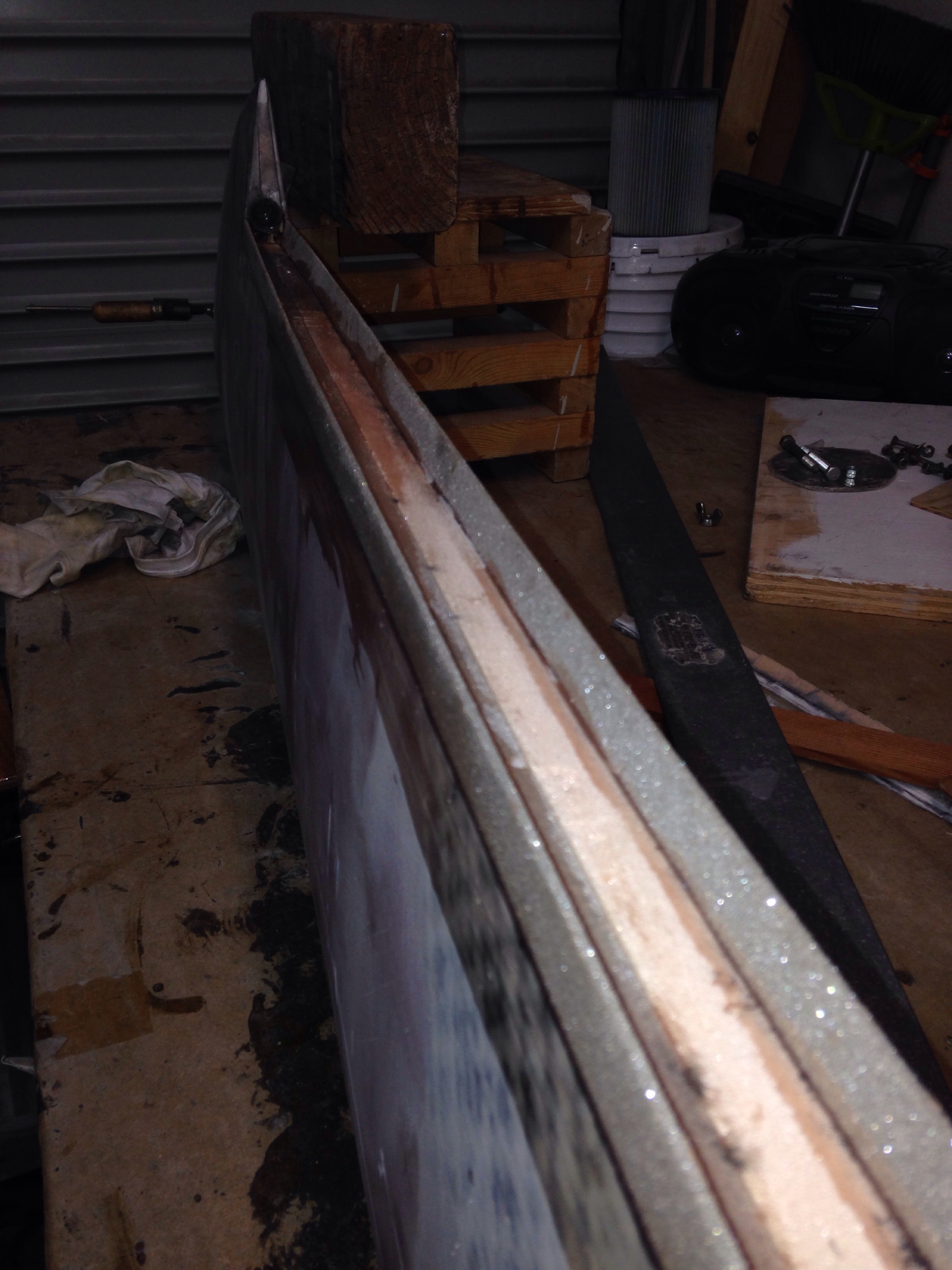
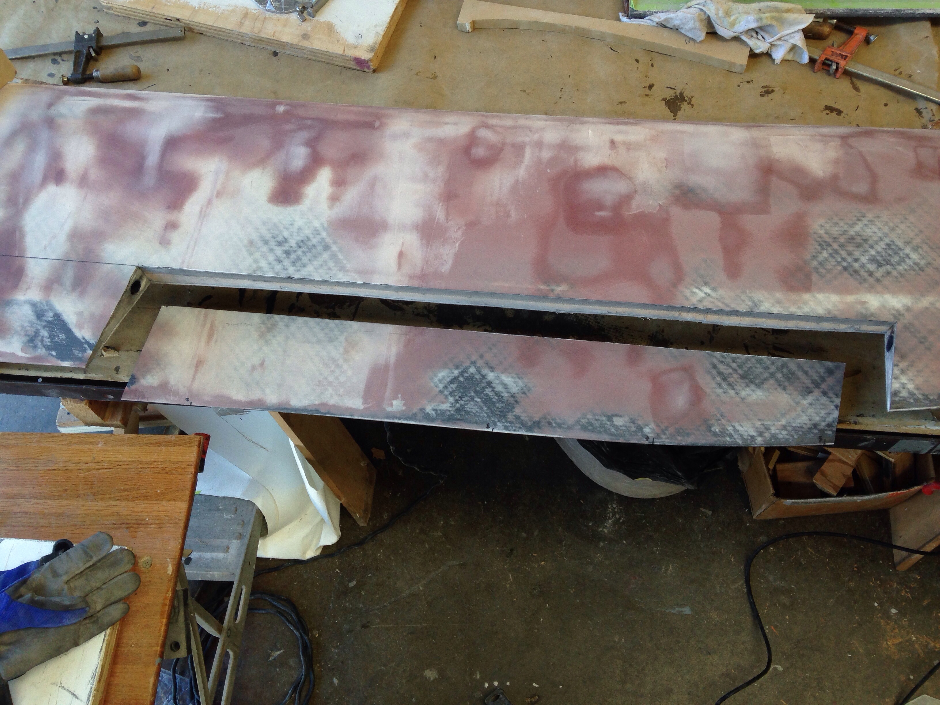
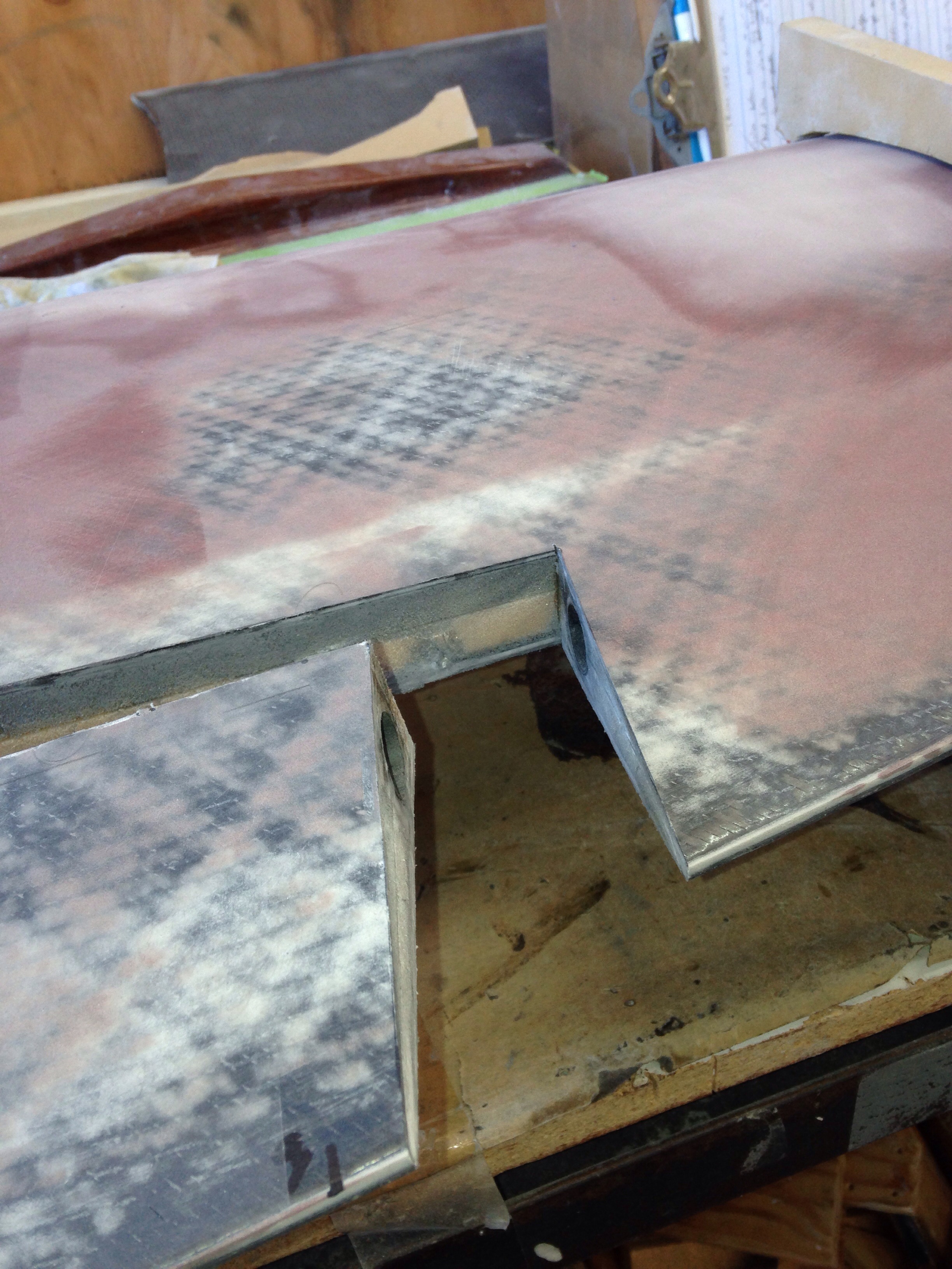
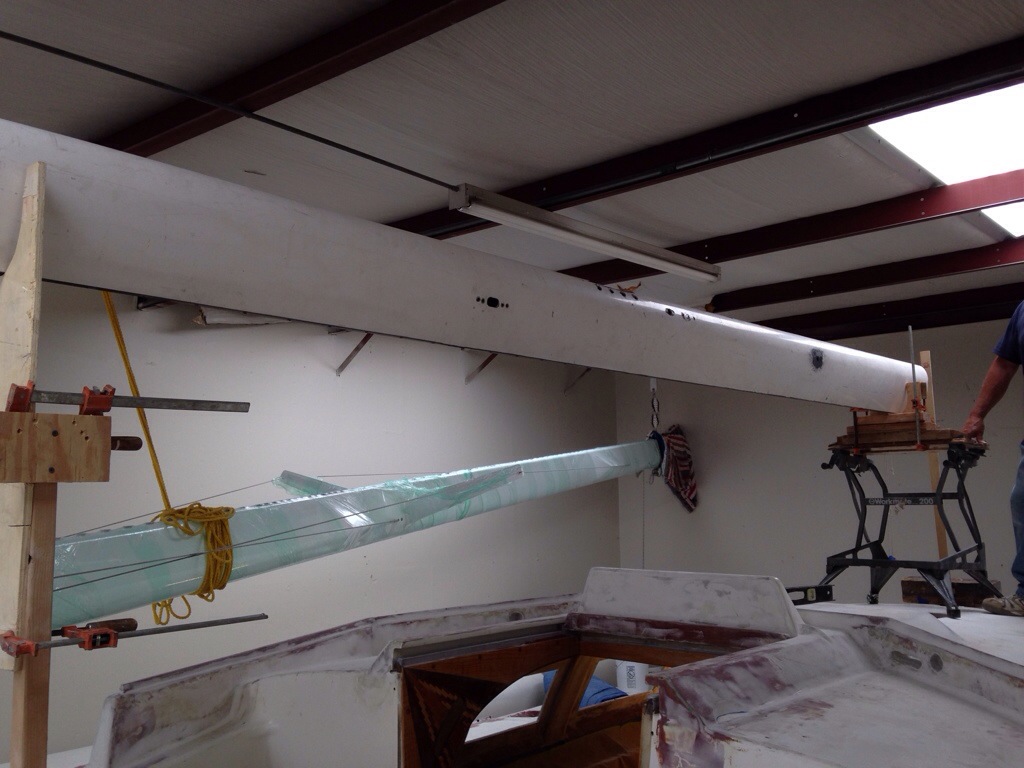
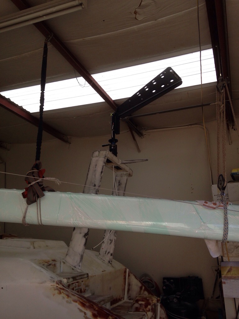
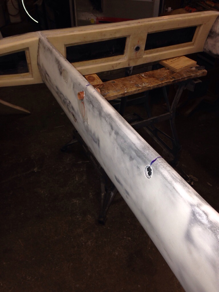
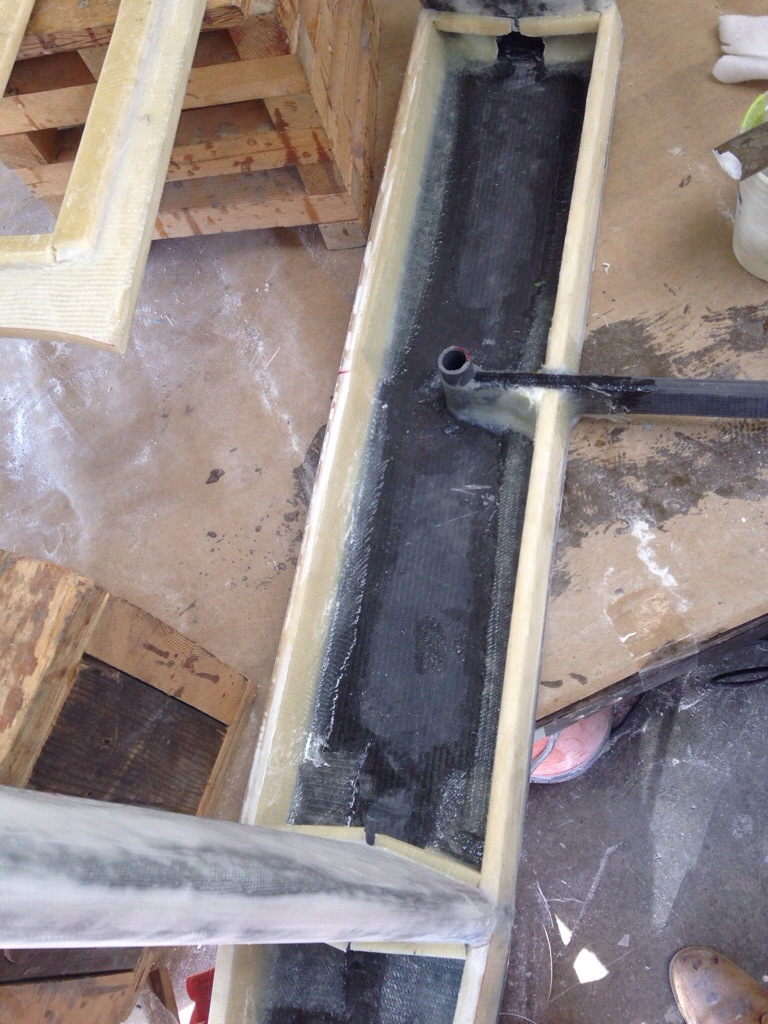
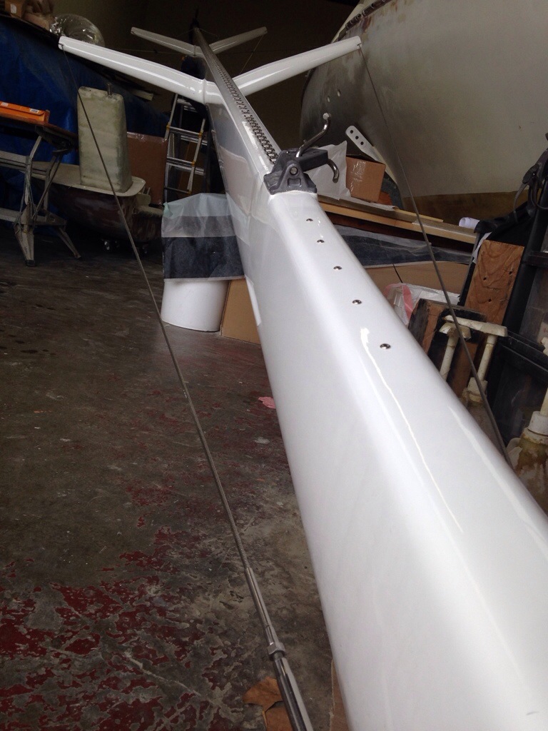
Today it was time to pull out the old mast segment we’ve had squirreled away and start creating the main boom. This stick is 18′ of a salvaged carbon mast. The section may be overkill but if we leave it as is, it should be a hell of a strong boom. One option is to cut away the last three inches off the skinny side and form a new, much lighter lower edge the whole length. Or we take Mike Leneman’s simple suggestion of making Swiss cheese holes all along the boom. That would also save weight and make it easy to run reefing rigging internally. And we also need to think through making sail catchers that stick out about a foot on both sides of the boom.

20141030-225421.jpg

20141030-225442.jpg

20141030-225453.jpg
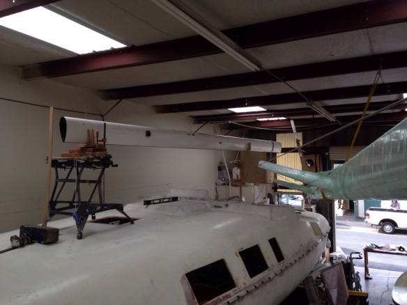
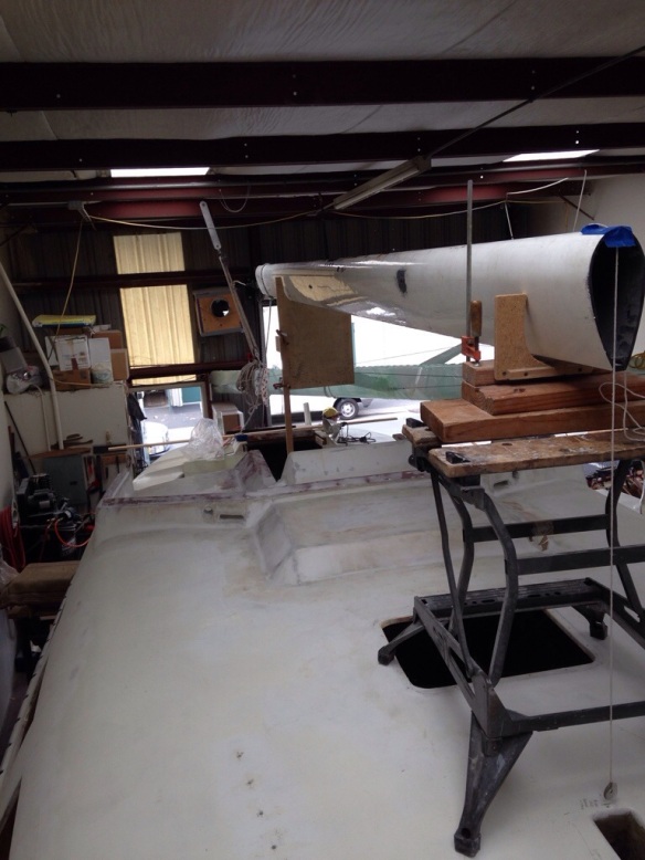
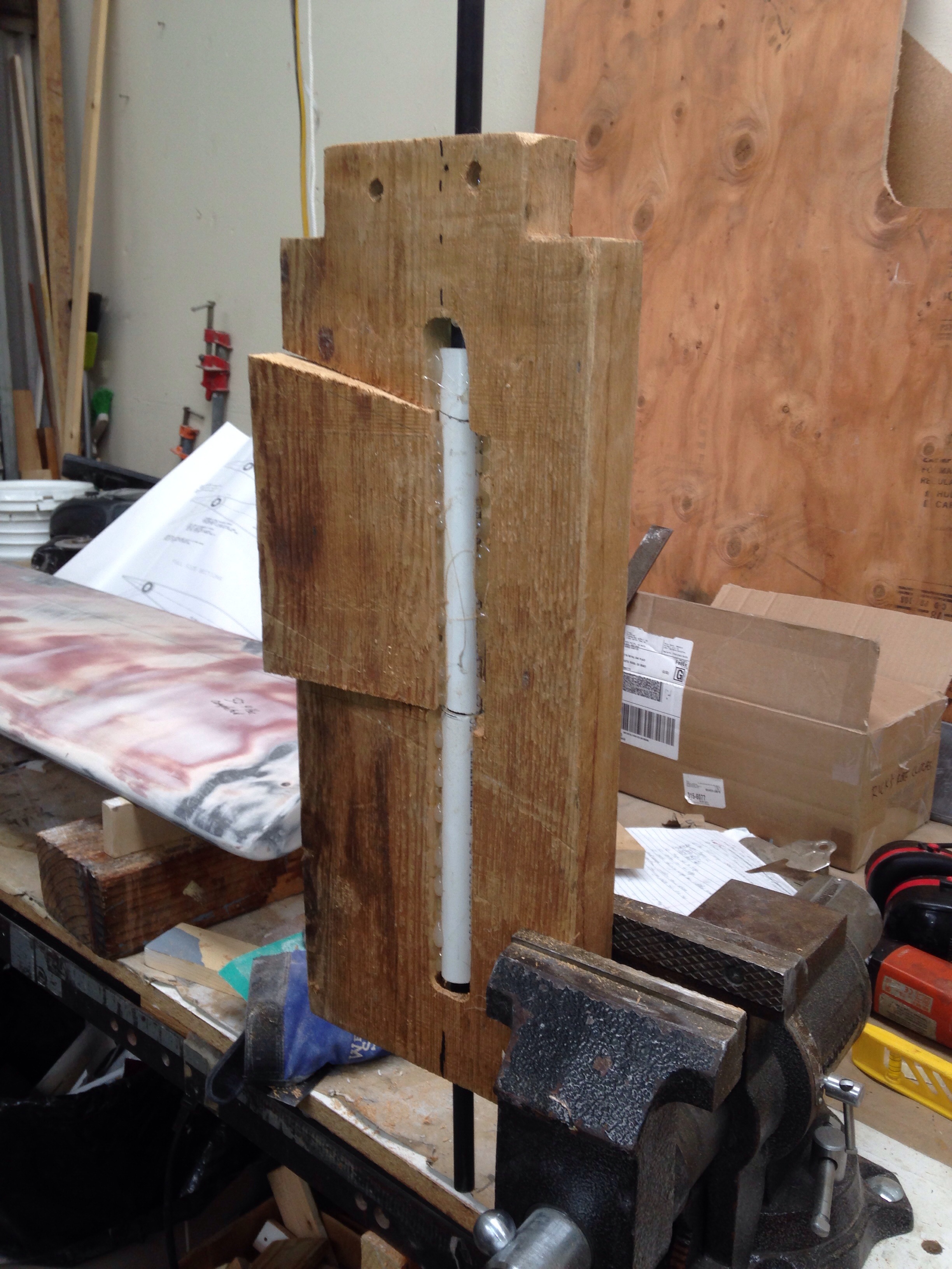
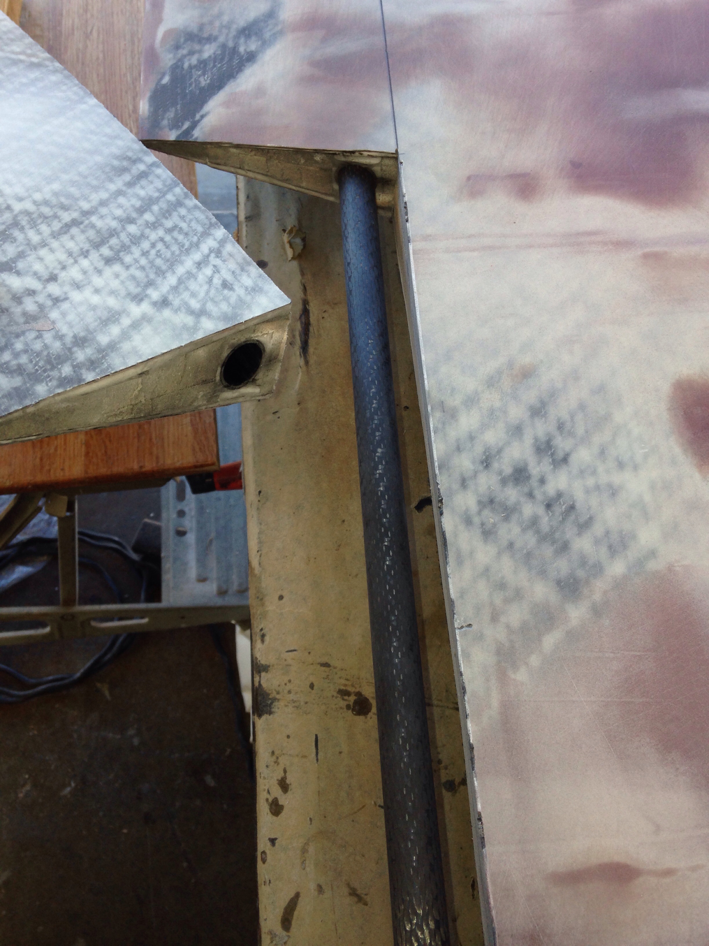
We started making a forward end bracket to bolt inside this boom, which will provide a strong pivot pin attachment to the gooseneck on the mast. One big bummer is that goose is already bedded and bolted to the mast at 54″ up (for the Shuttleworth it was commissioned to) but we need it a foot lower (that would get it to the level resting position seen in these sawhorse holding photos). Can’t really do that mast work until the boat is out of the workshop. Hmmm. The next update should have that boom end bracket to show you. And yes, the boom in this position shown is 6’3″ above the cockpit floor so fewer whacked heads expected. It’ll be about a foot above the hard top, leaving room for some solar panels up there.

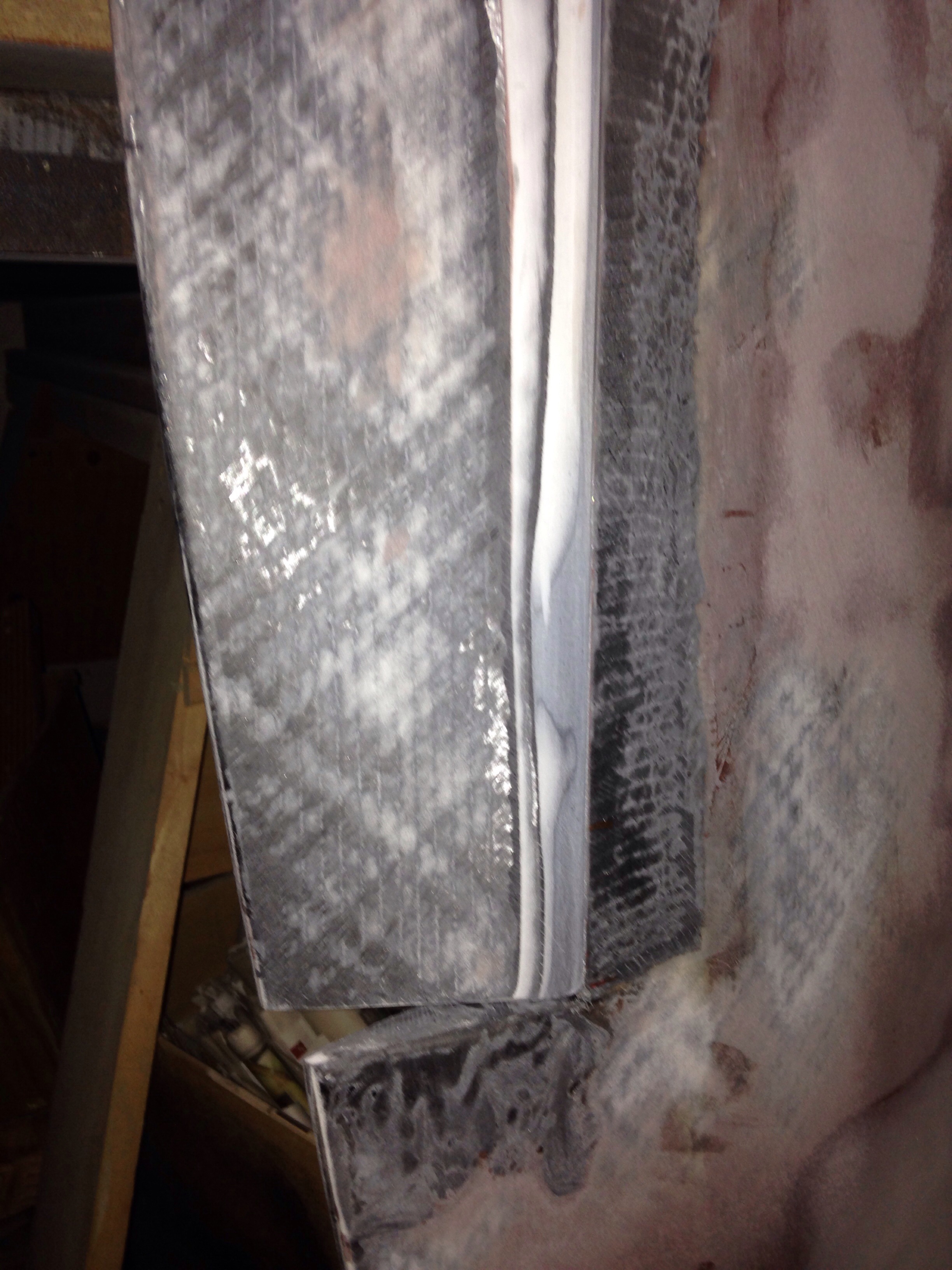
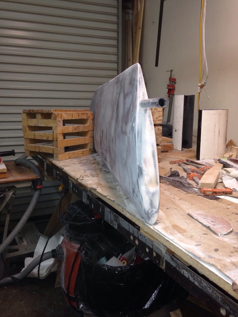
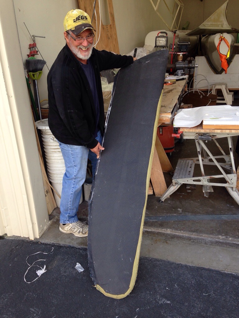
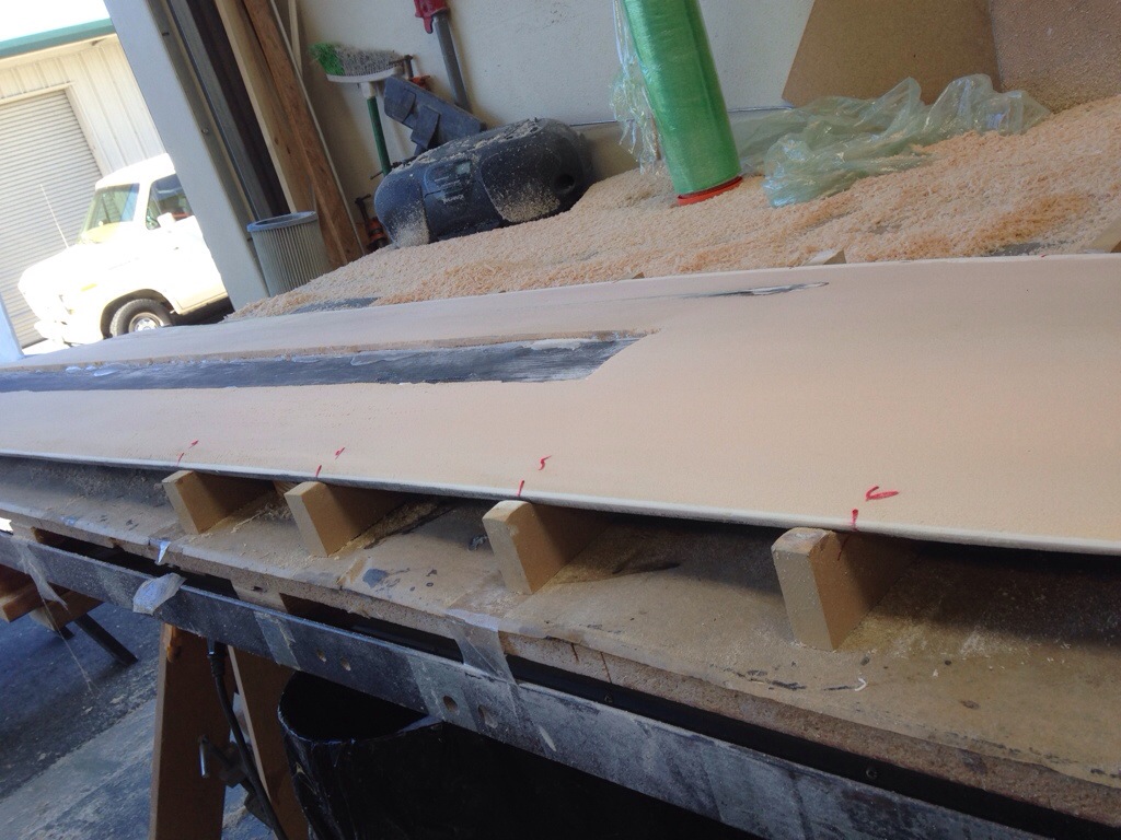
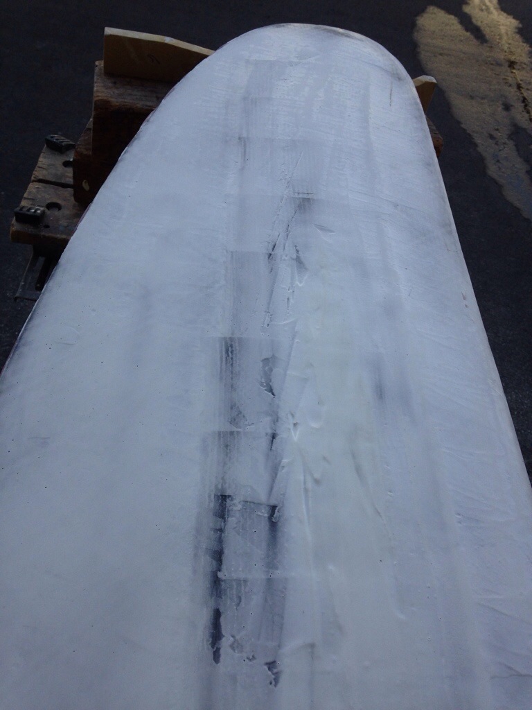
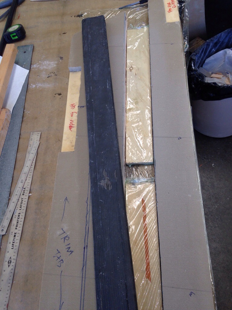
The rudder came out of its final carbon layer vacuum bag this morning, looking good (and big next to a grown up!)

20141030-230112.jpg
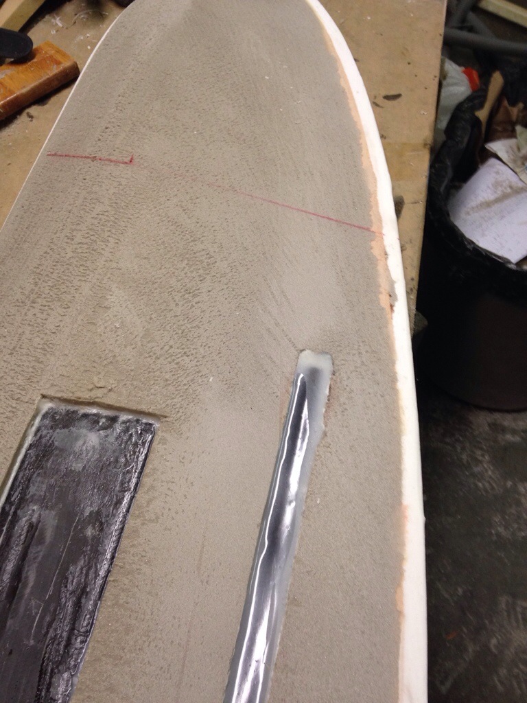
The yellow strip is a Kevlar piece to help make the leading edge tougher against hitting small stuff in the water. I’ll do a bit more final fairing on this board over the next couple of days and then it will be time to make the scary cut into it to creat the trailing edge trim tab. Cover your eyes, Mertyl, this one’s not for the faint of heart.

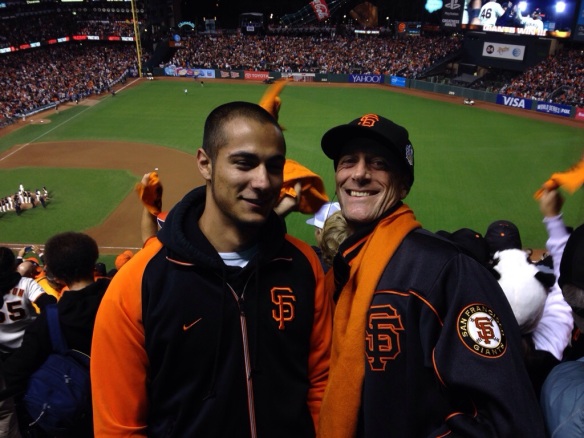
The boat has suffered some October down time due to excessive viewership of the SF Giants run. The prudent move would have been to purchase 10 gallons of epoxy, but instead the $ went to tix for Bumgarner’s shutout on Sunday.
Great time with Griffin!

20141030-230722.jpg
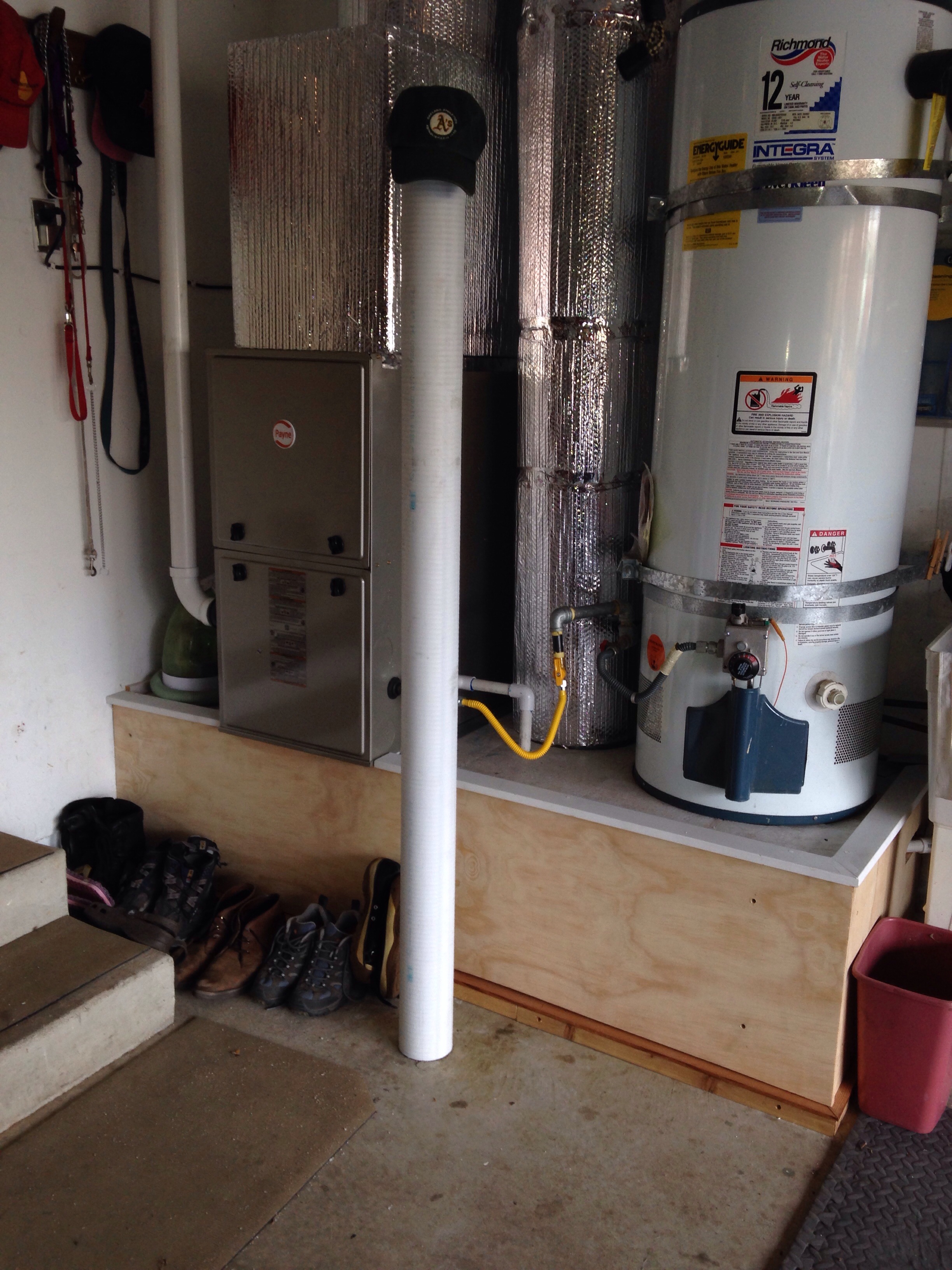
But World Series parades also mean it’s time for the weather to turn. Cold epoxy does not flow well, and I finally thought it through – make a winter warming hut! This simple box (old Sheetrock and leftover styrofoam) is now keeping the fluids at just right viscosity, with an air temp in the upper 70s. Venting the box more or less lets us modify the temperature and therefore adjust the go-off timing of the epoxy hardener. REALLY wish I had spent the two hours on this box two winters ago :(

20141030-231211.jpg
It’s warmed by a simple incandescent 60 watt bulb under an aluminum plate holding up the bottles.

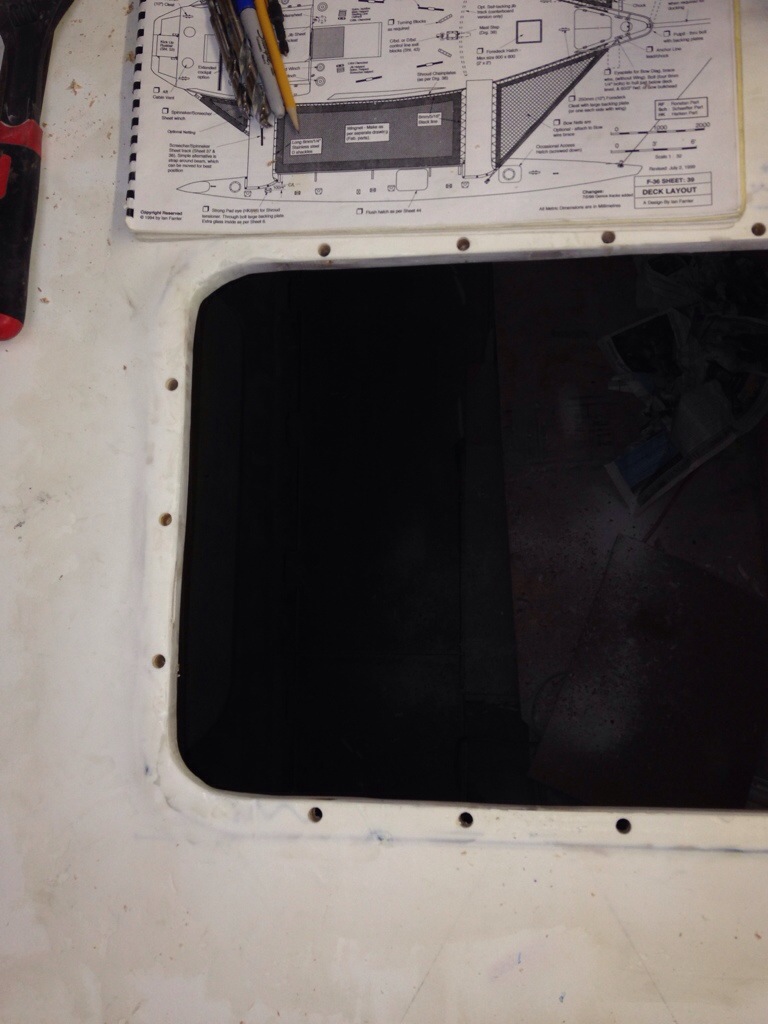
Good things are happening building out the aft cabin furniture. Photos to come once the bunks are bonded in. Yes, doing some work on the inside even though I said no cabin work until all exterior parts are complete. Thankfully it means we’re getting to the end of the outside stuff and can see the light towards the winter interior build. We’ll skip the Giants parade and work on the rudder!

Wind vane and rudder progress

The shop neighbors who were perplexed by the stern tower were satisfied now by seeing the self-steering wind vane installed. It’s the brown unit in these photos. The actual vane that gets pushed by the wind is in a deeply “reefed” position, tilted way back to fit under the skylight ceiling.

20141022-191941.jpg

20141022-192013.jpg

20141022-192043.jpg

20141022-192117.jpg
The rudder control cables come thru the tower shelf and will get tied to the legs and then routed to the (to be built) yoke atop the new rudder’s trim tab pivot pin.

20141022-192353.jpg
We’ll get back to those details in a couple of weeks when the rudder cassette is built.

The rudder has been shaped, wrapped once in bi-directional carbon and had the 14 layers of carbon unidirectional cloth added in the recessed channels down both sides of the board. First, here’s a look at how that embedded pivot tube just fits inside the shaped rudder.

20141022-193430.jpg

20141022-193449.jpg

20141022-193514.jpg
And underneath the white fairing compound you can just see the staggered layers of carbon uni.

20141022-193657.jpg
The only unexplained part of the rudder plans is how one would keep the blade’s curve intact over the area that gets cut out of the foam core and replaced by that big carbon-wrapped spine piece. So we have a flat spot there that I’ve had to build back up with fairing compound. I’m doing the fairing work now, before adding the final outer layer of carbon wrap.

20141022-194317.jpg
Ok, that side is done and we’ll need a few fairing sessions to finish the other.

While the rudder layers cure, work progresses on prepping the windshield and hardtop for paint, and the floors for the aft cabin and equipment room. Pictures soon.

Charlie gets sucked in

F27 owner Charlie Jeremias apparently didn’t get too turned off during the SoCal TaTa rally with me prattling on about the boat build; in fact he wanted to come work in the shop. So we figured a good day of vacuum bagging work would be fun. (Now if I could just get him back here to do the fairing…)
We tackled the last of the net lashing tubes – the 14′ sections on the float decks. Here’s the 3/4″ PVC bonded to the deck with epoxy putty fillets:

20141011-234801.jpg
Then I had to hurry with the wetting out of the fabric rolls as Master Glasser Charlie confidently laid out the 3 layer lamination:

20141011-234945.jpg
Here we’re ready to add the peel ply, perf’d film and breather before closing up the bag:

20141011-235108.jpg
Then with the vacuum pump running we focused on the replacement carbon tube to encase in the rudder stock (next topic). The next morning I happily unpacked the bagging supplies from the float deck to see our new net lashing tube bonded in place. Came out just fine.

20141011-235537.jpg
Once these tubes get faired and we cut the notches (same as was done on the beams and main hull), the float exteriors will finally be DONE!

Now back to the new rudder. At least the $100 Rockwest Composites carbon pivot tube showed up within 48 hours, so we’re quickly back in business. Charlie cleaned out that channel in the foam core to reset the proper depth. This time I used a more viscous epoxy and cabosil mix and pushed the tube in to a shallow puddle, and let that cure overnight. The next day saw further filling of epoxy mix to encase the carbon tube.

20141012-000150.jpg
Now it’s game-on; get to shaping the rudder out of the foam core stock! This time I only cut three depth lines with the circ saw and went right to the power planer. The long process I described months ago on the first rudder was cut down by about 75%, and this one is being shaped better too. But of course if you don’t mind the power cord, the machine quickly chews it up.

20141012-000509.jpg under the cord in that photo you can see the depth guide lines cut where the rudder face will be 1/2″, 3/4″ and 1″ out from the centerline. Didn’t bother to spray paint in the grooves this time as they are easy to spot as you plane away the stock. The trick is to leave a good 1/8″ or so to do by hand (shur-form) and not take the planer down to the depth contour line. Also, looking at Jim Antrim’s plans for the rudder trim tab I knew that carbon pivot tube would be close to the newly exposed rudder skin surface. Sure enough, you can see that it will lie about 1/16″ in to the remaining foam area. Tonight I back filled that channel back to flush with the rudder face – but here it is before filling in the gap:

20141012-001159.jpg
Tomorrow we’ll finish smoothing out this first rudder side, and when satisfied with the shape we grab the carbon fiber 12 layers of 6″ wide that needs to have more of the foam core rebated back to add this stiffener fabric. That step will make more sense with tomorrow night’s photos.

Stern tower finished

Here are a few more views now that the equipment tower is fabricated and faired. It will be getting a second horizontal ‘shelf’ but we’ll wait on placing that until figuring out if an electric tiller pilot (remote steering) can be mounted back there. This would be in addition to the primary windvane (no electricity needed) self-steering gear. We need to have the completed tiller in place first.

The legs have thru-holes for lifelines:

20141006-233754.jpg
The top is a carbon deck and a simple hollow box below with access ports to hide the equipment fasteners and wires. The hole in the center of the platform is a channel to pass the windvane’s control lines down to the rudder trim tab. And the horizontal stick out the back is a little gantry for lifting and holding the rudder out of the water once docked or anchored. The ear flap on the starboard side is for the radar; the port side is flush son you can get to the aft steps easily.

20141006-234119.jpg

20141006-234136.jpg

20141006-234155.jpg

20141006-234226.jpg
I’m actually getting sick of the splotchy fairing patches look on all these big parts. It’s about time to get things primer painted so a cohesive boat begins to emerge. But we shouldn’t touch any painting until the fabrication work is complete.

After the Jim Antrim meeting the steps on building the integrated trim-Tab rudder became clear, so work is underway. During careful placement of the 5′ carbon hinge tube, we had a “runaway thermal event”, meaning Greg blew it by trying to bond the 7/8″ carbon tube in to the centered 1 9/16″ channel cut into the foam core, and expecting to have that work in one fill ‘er up with epoxy putty pass. As I was seating in a uniform depth, the mass of wet epoxy down at the bottom was too great and it superheated quickly. Realizing the problem, I tried to yank the whole tube out and quickly evacuate the putty. Instead the carbon melted and bent the tube that needs to stay arrow-straight. What a huge mess, along with the panic of losing the very expensive 2 1/4″ shaped foam core and triple layer carbon spine. Here’s the work before the meltdown.

20141006-235307.jpg that’s the spine about to be bonded in – 3 layers of carbon around high density foam, then center the whole thing in the low density rudder core. Also see on the left side the marks for the trim tab – it’ll be 4 1/2″ of the 16″ wide rudder and run about 3′ vertically.
So Monday morning began with another $100 sent to Rockwest Composites in Utah to replace the pivot tube. Monday night ended with a nasty two hour job of extricating the ruined tube and hardened putty from the soft rudder core. skilsaw, router, grinder and multi tool teamed up to make a fantastic mess but in the end the channel integrity is back and ready to take the new tube once the UPS truck drops by. We’ll do the bonding in multiple stages this time. Another expensive lesson learned.

There’s strength in the sleeves

Building the beam sockets in to the float hulls last year was an interesting lesson in how much structural stiffness can be achieved by close-fit sleeving of two parts. Since we need the stern tower to be demountable for trucking, the sleeve method sounded like a good thing to try. And the results came out great.
Here are the permanent stubs waxed and ready for the tower legs

20140927-203752.jpg
Then the tower legs got bolted in place on top of the stubs, and the carbon wrapped around the stub-leg stack.

20140927-203924.jpg
With that lousy experience many months ago of the beam socket getting stuck on the beam, this time we went with overkill of multiple techniques for non-stick:

20140927-204139.jpg
Once the carbon and glass combo wrap cured, we released the thru bolts inside the aft cabin, and with a little tap the new sleeves legs popped right off.

20140927-204319.jpg

20140927-204427.jpg
With a bit of cleanup trimming around the bases, and pulling out all that wax paper, the finished legs are getting some fairing compound and are ready tomorrow for mounting the cross plates, forming an equipment tower. The sleeved legs are already solid as a rock without the horizontal pieces to tie them together – yea! And the whole tower is coming in at about ten pounds and all hidden internal wire handling. MUCH happier than an expensive, heavy, corrosion prone metal one. Epoxy goo and carbon fabric are fantastic :)

45 feet of ugly

20140926-202305.jpg
Rumor has it a nasty old single-wide mobile home has come back to life as a multihull boat support vehicle. So while you wouldn’t trust this thing for any human activity, Stephen’s old trailer did a great job hauling our mast the last 200 miles west from Toronto. The mast had piggybacked on a Formula 30 cat (which looks great and is for sale in Reno) and made it to the Marcoe’s side yard. It was a HUGE relief to finally get this thing tucked away in the workshop. Jeanne and Griffin were heroic in figuring out wedging the 50′ into the 48′ shop.

20140926-202911.jpg

20140926-202926.jpg

20140926-202942.jpg
Although I had seen the mast last fall in Canada, today is a fresh reminder of how nice it looks and the quality of workmanship used. Because it was designed for a different boat, and was built 6-7 years ago but never used, the delivery trip took a detour to naval architect Jim Antrim’s office on Tuesday for a professional opinion on the suitability for our boat. Eagerly awaiting his report.
Wednesday morning was consumed with cleaning the mast from years in storage and the transcontinental drive. The last photo today is for Jimbo – as if you were standing there directing me, after the bath the whole thing got wrapped in movers’ stretch plastic so it’ll be all fresh for the launching day!

This afternoon was a special treat while glass work on the hard top and stern tower cured. It’s time to install SAILING STUFF!

20140926-203735.jpg
Everything is based off the hull centerline and the center pin of the mast. Basically a big geometry exercise to plot out the halyards exiting the mast base and running back through the windshield holes. The jib car track placement comes from the plans.
All bolts are getting oversized drilling; next up is backfilling those holes with solid epoxy putty, then re drilling holes using the bolt diameters. This process prevents the soft cedar core from compressing when the bolts are tightened. See the too-big holes all around the ceiling hatch.

20140926-204214.jpg
We’ll figure out how to do this same process but with recesses on the bottom of the boat where the plumbing through-hulls can be made flush for streamlining. Saw that done on a custom boat and it is great.

Ok, small detour tomorrow, having to make the 450 mile round tripper to take the big blue meanie trailer back to Reno. Really hoping it doesn’t rain or spit snow on those bald tires!

20140926-204748.jpg

Hard top progress

I should call it a dodger, but that’s just not possible for a diehard Giants fan. Anyway, the roof over the main companionway got started today. First up was the solid corner panels above the side windows.

20140918-183728.jpg
The top panel is cored with 1″ foam board; decided to go with the forgiving/flexible Home Depot stuff ($10 a sheet) instead of fighting a $200 sheet of divinycell.

20140918-183929.jpg

20140918-183939.jpg
It’s held in place via holes, string and backing blocks until the outside layers of fiberglass set up tonight.
Using a layer of 12oz bidirectional and one heavy unidirectional. Will probably do the same on the underside and see how rigid the resulting structure turns out. Got a nice idea for an upturned lip around the aft edge, to give strength, a big hand hold, and deflect water out of the cockpit. Saw this in practice on Jim Milski’s beautiful Schoinning 44(?) catamaran he built in ’09.

20140918-184422.jpg
Also went aboard Roger and Dianna’s Catalina 470 Di’s Dream in Catalina last weekend and saw all kinds of on deck improvements for boat handling. Here’s his solar panel mount on the hardtop:

20140918-184626.jpg
And these ring-nuts used in many spots make great multipurpose anchors …

20140918-184724.jpg
And I have to find these simple line snubbers / beer can cozies! Great for saving hands when releasing lines thru the clutches while the winch is occupied:

20140918-184858.jpg
The anchor locker is an already vented place for dinghy gas, and that black tackle on the right provides slack relief from the windlass when he needs to work with the chain:

20140918-185032.jpg</a
And here's a really nice alternative to the big granny bars on a deck – do a mast-mount hand and line hold instead:

20140918-185137.jpg
All the boat visiting occurred during the SoCal TaTa hosted by Latitude38. Jim brought Origami to the shop for a prep day then we towed to Santa Barbara for a fantastic weather Channel Islands week. Our little 27 footer was the fastest boat in the fleet, beam reaching faster than 60 footers!
Can’t even imagine what the big new tri will be like in those ideal conditions. Hopefully next summer will tell!

20140918-185621.jpg