starboard beams ready for their tops

It’s been two months since a post because progress has been tedious with many little steps to finishing the internal webs / structures inside the beams. And severely limited building hours due to lots of business travel. In the photo the ‘wings’ just inboard of the sides, plus the brown foam along the center, are glueing attachment points for the beam top. When sealed up, the glue joints complete the box structure for final rigidity. The tops will never be able to come off without major surgery. Image

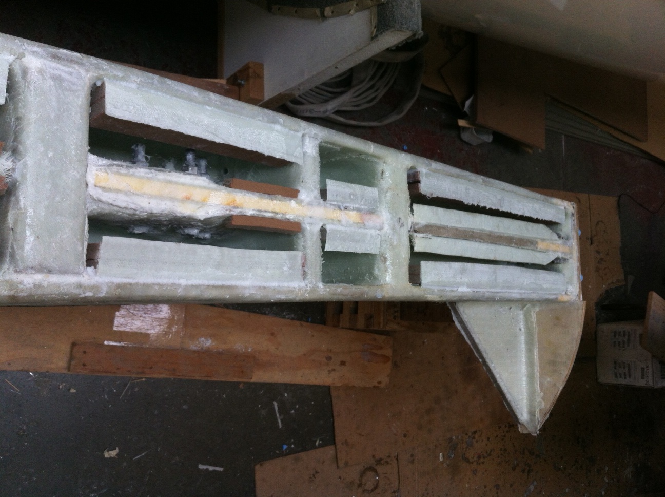
Now the fitting and internal structure of the port beams is underway. Spent all day Sunday with Griffin’s help repositioning the workshop to slide the main hull six feet to the right. This included taking one of the 35′ float hulls out in the street, which always gets the neighbors buzzing. 

While building the internals of the starboard beams, most of the pieces for the port side were also constructed, so construction should go much faster (including not repeating some time-wasting methods used the first time). The plan is to get all four beams ready for sealing, then build the four top pieces all at once. Then it’s on to the wrapping laminations, and building the fairings. At this rate, these beams will consume all of 2012. Slow and steady and rock-solid – just following Farrier’s documents with all the big warnings about “Do this part right!”


PS – the GORGEOUS 50′ carbon rotator mast has been purchased, and is awaiting transport west…  More on that later – yea!!!

Trial fitting the beam cores

OK, now it’s starting to feel like a multihull! With the beams set up, we got our first taste today of how big the main nets are going to be – lots of room for stargazing evenings.

Big thanks to Dad for the painstaking drill press and cutting work on the 8 aluminum tangs that emerge from the beam bottoms and attach to the diagonal braces. Those braces are about 3 ft long, made from heavy 1/2″ stock. The plans allow them to be narrowed down to 2″ along most of the length. I think after all the trial fitting they’ll go to a cutting shop to remove that extra weight, but more importantly when they are narrower, I’m thinking it’s less surface area for waves to hit on the leeward side.

The second photo shows the positioning of the tangs inside the beam. The web they attach to is 12lb high density foam with six layers (each side) of 18oz bi-directional fabric, alternated 0-90 and 45-45. This is some of the beefiest fiberglass construction on the whole boat. Next week is a multi-step process of positioning the metal precisely on the web using wooden dowels, then glueing one tang at a time, drilling out the dowels and replacing with bolts, etc. etc. Many more hours of permanently hidden details :)

looks like the boat is stretching out its arms for the first time

note to other F36 beam builders:  plans call for putting the ‘wings’ on the top of this web before you glass the web in place (same as the beam-attach web in the top of the photo). Having those wings in place made it really difficult to work on the tabbing-in. This time I’m leaving them off for now, and once tabbed in the beam, will go back and add wings with the similar method Farrier wrote for attaching the full side-widening edges just before installing the beam tops.

They fit!

at least the starboard beams do anyway… tonight was drilling the holes in the ends of the beams to accept the big 1″ diameter main bolts. Plans call for bonding the bolts in place right away, but I needed to do a dry-run fit because it was worrisome about how these holes would line up exactly. It was hard in my mind because the beams are not at their final exterior dimensions yet, so you can’t just plop them in location and trace the hole. It’s careful transcription of the plans on to templates then the stock, etc. Here’s the first beam being tested in place.

The rear one fit too. They’re back down on the ground now to have the bolts permanently bonded in, and the slices on the bottoms cut for the diagonal brace upper-end tangs. After the starboards are all fitted, measured and bonded in position, we’ll take it all down and rearrange the shop to move the boat over to fit the port beams (hopefully still in June).

Main hull bracket plates for beam braces

The slices on the hull sides shown in the last post allowed the starboard forward bracket plates to be installed. These are now the anchors for diagonal braces that will attach to the bottom of the beam(s). Here they are bonded and bolted in place, but a lot of finish work to do around the edges. This pair of plates is being installed after the floor went in and the forward cabin closet built. Not ideal, as I had to cut in to prior work and will go back for touch-ups. Some of the compromises when you’re buying stock based on budget, availability and time!

Exact location of these plates is acheived thru a clever jig that bolts in place at the primary beam bolt holes, and holds the brackets for position marking before final bulkhead laminations, and then again while you do the actual bonding and bolting application. Note we’re using little aluminum tubes the same size as the real bolts to work around the brackets being so close to the boat’s cradle.

Cutting in to a perfectly good boat hull

Putting holes in the boat way above the waterline doesn’t seem too crazy. The beam bolts need 1-1/16″ holes perfectly positioned in the beam recess area – these are big holes to drill, going slowly and using a lot of lube oil to keep the bit cool enough heading through the very thick aluminum plates inside the boat. Dug out the big drill for this job.


But slicing a couple of 19″ shark-gills down low is spooky!  By the time the beam brackets are bonded in here, and many layers of filling and fairing take place, these big holes in the boat will be long forgotten – but right now it looks awful to see the light coming through at the waterline.

forward of the two cuts that go down here


The bulkhead where these brackets attach was prepared tonight with more laminations for structural strength, and we’re ready for a Memorial Day install of the final beam brackets so we can get to trial fitting the beams perhaps next weekend. Getting excited to see how big it all looks mounted together. It’ll take a lot of pushing the hulls around, as the full beam of the boat is a few feet wider than the workshop. Darn.


What’s inside the beams

This month is all about doing work hopefully no one will ever see. There’s a lot of intricate structure inside the box beams, and once the tops go on next month, the “innards” will be sealed in forever. First up are the beam bolt connection brackets that got attached to the webs shown in the last post. Here are the assembled pieces, with their ‘wings’ on top. Those make a wider grab space for affixing the beam tops. I installed these four inside the beams today, then went on to finishing the last big aluminum bracket plates that bolt to a forward bulkhead and stick out of the hull to receive the beam struts.

final pair of bracket plates – other 3 sets are already installed


what’s inside the beams

Aside

Here are four copies of the web that will go on the inboard end of each beam. After curing each one gets an angle-bracket assembly on the end, and those will form the backing attachment point for the big 1″ thick main bolts (that secure the beams to the hull).

Tonight’s lamination, including cutting out 40 pieces of various cloth fabric and prepping the epoxy, was after dinner, from the 5th thru 9th innings of the Giants/Phillies game (bumgarner got the win). So about 1.5 hours in/out of the shop, which is about all I have available on weekdays. We’re not pursuing any vacuum bagging because I think it would take more time, so lots of little steps wouldn’t happen every possible day – and the boat would take more years! That’s the rationale, anyway.  So what happens instead of bagging?  Peel ply, then some plastic sheeting, and low tech pressure…

Ready to break the mold

Finished the core of the final (aft port) beam, so we get the satisfaction of busting up the beam mold. The plans called for 3/4″ particle board, but I think OSB sheathing would have worked better. Particle board chipped and split too easily.

Ian answered my question about orientation of the DBM1708 (tape with red stripe in it) – I should have been using the non-backed DB170 cloth instead. Got a 100+lb roll – that has made covering the aft beams much faster.

We received 800′ feet of one-foot wide carbon fiber rolls this week, and the first layers went on the bottom of the Forward Starboard beam today. Amazing to think they’ll be getting 20 layers of carbon on the top side!

The resin is working really well

Researching which resin to use in the beam build led to lots of choices, a big range in pricing, and many opinions. At about 10 gallons in, and 3 of the beam-cores out of the mold, I’m really happy with the DR-5 “toughened” epoxy (and the corresponding EH-102) from Applied Poleramic in Benicia, Ca. Of course it’s a big benefit they’re within an hour’s drive from the shop, but more convincing was the fact they are ‘Farrier friendly’ and reportedly supplied the epoxy for a bunch of the F25 Carbons built in Colorado. They were very helpful over the phone as we talked about options, and I feel I’m using very high quality material at a very reasonable price (well under any West System prices I could find). The ratio is 4:1, which also helps keep the cost down (less hardener needed than some other systems).

The resin and hardener mix easily and are giving a nice long (about an hour) pot-life which is great for the long, repetitive laminations on these early stages of the beams. It takes the fillers well, too, so the putty-making has been straightforward.  Made a second visit to them in February, buying 3 – five gallon buckets this time. While it would be more economical to buy a big barrel, the convenience and ‘progress payments’ of the five gallon size seems right for this. I’m guessing it will be 20-25 gallons total to build the four beams.

For the first beam, I dispensed using the plastic ‘ketsup plungers’ straight from the big bucket. That was a huge drag, as it was difficult to heat the five gallon bucket enough to get a decent flow, plus it being critical to count every stroke. Finally got smart, stopped building for a day, and got the old StickyStuff dispenser pumps going again (they had seized up with encrusted hardener). Messy, tiresome job, but wow, these guys are the new heroes of the workshop!

They look a little funky, but the tank-internals are now clean and the dispensing tubes have been replaced. The unit on the left is a 4:1 mix system, and the right is a 2:1. Now we can make as little as an ounce of mixed epoxy, or very quickly do big pints in quick succession as needed for hand-layup. http://www.michaelengineering.com/  Had to call these guys with a question the other day, and they were great.

Aft starboard beam-core came out of the mold the other day, and tonight the first lamination of the 4th beam got underway. Hopefully by next week you’ll see a photo of all four beams lined up on the table starting to get the complex inner web systems underway!

Starting the Aft beams

The forward port beam popped out of the mold much easier. It’s in the front of the photo, getting it’s core-outer wrap layer. On the first beam I wrapped the tape transversely, but it was difficult to get a perfectly flat lie on all surfaces. So we’re trying the second one down the length of the beam instead. The tape is DBM1708 45/45 angles, so I don’t think the orientation matters for strength. Running crosswise on the first one left lots of ridges to sand down.

Now it’s on to the aft beams. Same mold frame, but these two will be a few inches shorter. See the endplate moved inboard a bit at the bottom of the photo. Tomorrow this one gets its bulkheads installed.