They fit!

at least the starboard beams do anyway… tonight was drilling the holes in the ends of the beams to accept the big 1″ diameter main bolts. Plans call for bonding the bolts in place right away, but I needed to do a dry-run fit because it was worrisome about how these holes would line up exactly. It was hard in my mind because the beams are not at their final exterior dimensions yet, so you can’t just plop them in location and trace the hole. It’s careful transcription of the plans on to templates then the stock, etc. Here’s the first beam being tested in place.

The rear one fit too. They’re back down on the ground now to have the bolts permanently bonded in, and the slices on the bottoms cut for the diagonal brace upper-end tangs. After the starboards are all fitted, measured and bonded in position, we’ll take it all down and rearrange the shop to move the boat over to fit the port beams (hopefully still in June).

Main hull bracket plates for beam braces

The slices on the hull sides shown in the last post allowed the starboard forward bracket plates to be installed. These are now the anchors for diagonal braces that will attach to the bottom of the beam(s). Here they are bonded and bolted in place, but a lot of finish work to do around the edges. This pair of plates is being installed after the floor went in and the forward cabin closet built. Not ideal, as I had to cut in to prior work and will go back for touch-ups. Some of the compromises when you’re buying stock based on budget, availability and time!

Exact location of these plates is acheived thru a clever jig that bolts in place at the primary beam bolt holes, and holds the brackets for position marking before final bulkhead laminations, and then again while you do the actual bonding and bolting application. Note we’re using little aluminum tubes the same size as the real bolts to work around the brackets being so close to the boat’s cradle.

Cutting in to a perfectly good boat hull

Putting holes in the boat way above the waterline doesn’t seem too crazy. The beam bolts need 1-1/16″ holes perfectly positioned in the beam recess area – these are big holes to drill, going slowly and using a lot of lube oil to keep the bit cool enough heading through the very thick aluminum plates inside the boat. Dug out the big drill for this job.


But slicing a couple of 19″ shark-gills down low is spooky!  By the time the beam brackets are bonded in here, and many layers of filling and fairing take place, these big holes in the boat will be long forgotten – but right now it looks awful to see the light coming through at the waterline.

forward of the two cuts that go down here


The bulkhead where these brackets attach was prepared tonight with more laminations for structural strength, and we’re ready for a Memorial Day install of the final beam brackets so we can get to trial fitting the beams perhaps next weekend. Getting excited to see how big it all looks mounted together. It’ll take a lot of pushing the hulls around, as the full beam of the boat is a few feet wider than the workshop. Darn.


What’s inside the beams

This month is all about doing work hopefully no one will ever see. There’s a lot of intricate structure inside the box beams, and once the tops go on next month, the “innards” will be sealed in forever. First up are the beam bolt connection brackets that got attached to the webs shown in the last post. Here are the assembled pieces, with their ‘wings’ on top. Those make a wider grab space for affixing the beam tops. I installed these four inside the beams today, then went on to finishing the last big aluminum bracket plates that bolt to a forward bulkhead and stick out of the hull to receive the beam struts.

final pair of bracket plates – other 3 sets are already installed


what’s inside the beams

Aside

Here are four copies of the web that will go on the inboard end of each beam. After curing each one gets an angle-bracket assembly on the end, and those will form the backing attachment point for the big 1″ thick main bolts (that secure the beams to the hull).

Tonight’s lamination, including cutting out 40 pieces of various cloth fabric and prepping the epoxy, was after dinner, from the 5th thru 9th innings of the Giants/Phillies game (bumgarner got the win). So about 1.5 hours in/out of the shop, which is about all I have available on weekdays. We’re not pursuing any vacuum bagging because I think it would take more time, so lots of little steps wouldn’t happen every possible day – and the boat would take more years! That’s the rationale, anyway.  So what happens instead of bagging?  Peel ply, then some plastic sheeting, and low tech pressure…

Ready to break the mold

Finished the core of the final (aft port) beam, so we get the satisfaction of busting up the beam mold. The plans called for 3/4″ particle board, but I think OSB sheathing would have worked better. Particle board chipped and split too easily.

Ian answered my question about orientation of the DBM1708 (tape with red stripe in it) – I should have been using the non-backed DB170 cloth instead. Got a 100+lb roll – that has made covering the aft beams much faster.

We received 800′ feet of one-foot wide carbon fiber rolls this week, and the first layers went on the bottom of the Forward Starboard beam today. Amazing to think they’ll be getting 20 layers of carbon on the top side!

The resin is working really well

Researching which resin to use in the beam build led to lots of choices, a big range in pricing, and many opinions. At about 10 gallons in, and 3 of the beam-cores out of the mold, I’m really happy with the DR-5 “toughened” epoxy (and the corresponding EH-102) from Applied Poleramic in Benicia, Ca. Of course it’s a big benefit they’re within an hour’s drive from the shop, but more convincing was the fact they are ‘Farrier friendly’ and reportedly supplied the epoxy for a bunch of the F25 Carbons built in Colorado. They were very helpful over the phone as we talked about options, and I feel I’m using very high quality material at a very reasonable price (well under any West System prices I could find). The ratio is 4:1, which also helps keep the cost down (less hardener needed than some other systems).

The resin and hardener mix easily and are giving a nice long (about an hour) pot-life which is great for the long, repetitive laminations on these early stages of the beams. It takes the fillers well, too, so the putty-making has been straightforward.  Made a second visit to them in February, buying 3 – five gallon buckets this time. While it would be more economical to buy a big barrel, the convenience and ‘progress payments’ of the five gallon size seems right for this. I’m guessing it will be 20-25 gallons total to build the four beams.

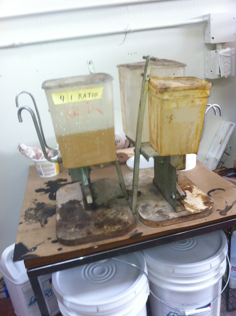
For the first beam, I dispensed using the plastic ‘ketsup plungers’ straight from the big bucket. That was a huge drag, as it was difficult to heat the five gallon bucket enough to get a decent flow, plus it being critical to count every stroke. Finally got smart, stopped building for a day, and got the old StickyStuff dispenser pumps going again (they had seized up with encrusted hardener). Messy, tiresome job, but wow, these guys are the new heroes of the workshop!

They look a little funky, but the tank-internals are now clean and the dispensing tubes have been replaced. The unit on the left is a 4:1 mix system, and the right is a 2:1. Now we can make as little as an ounce of mixed epoxy, or very quickly do big pints in quick succession as needed for hand-layup. http://www.michaelengineering.com/  Had to call these guys with a question the other day, and they were great.

Aft starboard beam-core came out of the mold the other day, and tonight the first lamination of the 4th beam got underway. Hopefully by next week you’ll see a photo of all four beams lined up on the table starting to get the complex inner web systems underway!

Starting the Aft beams

The forward port beam popped out of the mold much easier. It’s in the front of the photo, getting it’s core-outer wrap layer. On the first beam I wrapped the tape transversely, but it was difficult to get a perfectly flat lie on all surfaces. So we’re trying the second one down the length of the beam instead. The tape is DBM1708 45/45 angles, so I don’t think the orientation matters for strength. Running crosswise on the first one left lots of ridges to sand down.

Now it’s on to the aft beams. Same mold frame, but these two will be a few inches shorter. See the endplate moved inboard a bit at the bottom of the photo. Tomorrow this one gets its bulkheads installed.

Forward Starboard beam is underway

005’s plans were delivered from Farrier Marine 16 years ago; she’s got 3 nice hulls sitting next to each other, but not connected. 2012 is finally the time for the beams!  Spent New Year’s Day building the form out of 3/4″ particle board. In the interest of saving the lower back, we’ve lifted the whole works up about a foot on four heavy blocks – that’s been great so far during lamination.

“Forward Starboard” gets started. Grey foam is 5lb/cubic ft density, yellow is the no-compress 12lb. Diagonal brace tangs will be cut in to floor of beam in yellow section. Beam bolts go thru solid resin seen on the end-plate.

Core layers of DBM1708 tape laminated.


Each lamination step on the beams seems to take about an hour, so weekend days get second (and third) concurrent projects. Starting on the main hatch cover here. Secured the foam to the original hull cutout to get the right arched shaped.

Backing plate inside the instrument pod. planning on tacktick wireless, but Dad thinks I should install a wiring channel just in case. Not a bad idea.


ForwardStarboard released from the mold after bulkheads were installed. Didn’t use enough non-stick tape inside the mold; two spots of resin from seams got the particle board, causing a dumb half hour of careful prying and banging to get the release. All minor dings repaired. Yellow foam horizontal line is the zone for backing plate inside, to handle the trampoline lashing eyes.